
Contact Sensors Skin Acceleration Sensors Shape Sensor
 Project
groundwork has included development and improvement of tactile sensors compatible
with our telemanipulation system. Our first concern in integrating tactile
sensing with our telemanipulation system was to develop robust fingertip contact
sensors. Contact location is necessary for regulating internal grasp forces
during rolling operations. Our design utilizes an array of contact switches,
fabricated as part of a flexible printed circuit. The conductive traces of
the flex circuit, which make up one half of each contact switch, are distributed
around the circumference of the robot fingertip. The switches work much the
same way as keyboard membrane switches, except in our case thin strips of
dielectric tape seperate the conductive traces of the flex circuit from a
copper grounding foil. The design is simple, low profile and reconfigurable
for use in concert with other tactile sensors envisioned for our system. These
sensors detect a line of contact on the circumference of the fingertip, allowing
us to calculate a contact angle which is sufficient for control of our planar
robot hand. Future designs may include the ability to distinguish where the
contact was made along the depth of the finger. See below for more details
of the construction of our contact sensors.
Project
groundwork has included development and improvement of tactile sensors compatible
with our telemanipulation system. Our first concern in integrating tactile
sensing with our telemanipulation system was to develop robust fingertip contact
sensors. Contact location is necessary for regulating internal grasp forces
during rolling operations. Our design utilizes an array of contact switches,
fabricated as part of a flexible printed circuit. The conductive traces of
the flex circuit, which make up one half of each contact switch, are distributed
around the circumference of the robot fingertip. The switches work much the
same way as keyboard membrane switches, except in our case thin strips of
dielectric tape seperate the conductive traces of the flex circuit from a
copper grounding foil. The design is simple, low profile and reconfigurable
for use in concert with other tactile sensors envisioned for our system. These
sensors detect a line of contact on the circumference of the fingertip, allowing
us to calculate a contact angle which is sufficient for control of our planar
robot hand. Future designs may include the ability to distinguish where the
contact was made along the depth of the finger. See below for more details
of the construction of our contact sensors.
![]()
 We
also recognize the importance we place on dynamic cues during routine
manipulation tasks. Much of our ability to perceive object features or
roughness relies on our ability to sense dynamic events using cutaneous
mechanoreceptors. For this reason we have investigated methods for measuring
such events. Our design is based on the "skin acceleration sensor" presented
by Howe and
Cutkosky (1989). See below for more details of the construction
of our skin acceleration sensors.
We
also recognize the importance we place on dynamic cues during routine
manipulation tasks. Much of our ability to perceive object features or
roughness relies on our ability to sense dynamic events using cutaneous
mechanoreceptors. For this reason we have investigated methods for measuring
such events. Our design is based on the "skin acceleration sensor" presented
by Howe and
Cutkosky (1989). See below for more details of the construction
of our skin acceleration sensors.
![]()
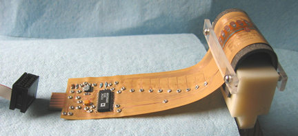
We are also investigating a sensor capable of measuring local contact geometry, which we call a "shape sensor". Local object curvature (along with contact location) is essential for planning finger motions during a given manipulation task. The sensor employs an array of strain gages with local signal conditioning deposited on a flexible printed circuit to measure local curvature directly (see figure below).
![]()
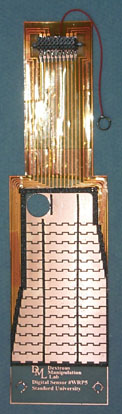
 A
flexible printed circuit is the heart of our contact sensor design. The conductive
traces of the flex circuit form lines around the circumference when wrapped
over the base of the robot fingertip. Each trace is seperated from a copper
grounding plain by thin strips of dielectric tape, making up an individual
switch on the circumference. The contact switch array works much the same
way as keyboard membrane switches. The sensor is covered with a layer of 3M
Greptile
skin.
A
flexible printed circuit is the heart of our contact sensor design. The conductive
traces of the flex circuit form lines around the circumference when wrapped
over the base of the robot fingertip. Each trace is seperated from a copper
grounding plain by thin strips of dielectric tape, making up an individual
switch on the circumference. The contact switch array works much the same
way as keyboard membrane switches. The sensor is covered with a layer of 3M
Greptile
skin.
These sensors detect 16 lines of contact on the circumference of the fingertip, giving us a a contact angle resolution of approxmately 6 degrees. Future designs may include the ability to distinguish where the contact was made along the depth of the finger.
We have designed simple interface electronics to multiplex digital outputs of two "16-bit" contact sensors into a standard 8-bit digital port on our robot's control card.
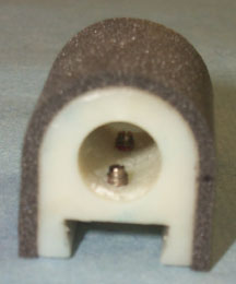 |
Robot Fingertip Base |
|
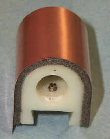 |
Robot Fingertip with Copper Grounding
Foil * Initially we used copper foil without mylar backing, but had problems with changing sensitivity of the contact sensors during use. We attributed these changes to small indentations in the foil over the strips dielectric tape. These indentations reduce the gap between the contact traces and the grounding foil making the sensors hypersensitive, registering false contacts. For more detail see below. |
|
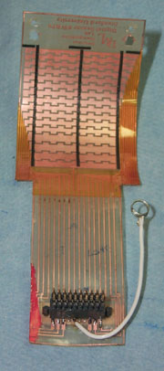 |
Contact Sensor flex circuit The flex circuit shown here is complete with 20-pin, 0.050" pitch connector (SAMTEC SFLX-110-T2-S-D), grounding wire (shown here as white) and the strips of dielectric tape (black vertical strips). These dielectric stips seperate the contact traces (the interlaced horizontal copper features to the left) from the copper grounding foil (shown above). The flex circuit was photoimaged using dipcoated copper-clad Mylar (Arlon 3 mil 1oz. laminate). The copper-clad mylar was dipcoated with (PC 179) positive photoresist at Injectorall. The connector is held on with small barbs which protrude through holes in the flex circuit into a small piece of 0.031 inch thick FR4. This sandwiches flex circuit between the connector and the FR4. The connector mates to a SAMTEC (FFSD-110-D-240.00-01-N) (.050" pitch) ribbon cable using a FTSH-110-01-L-D header.
|
|
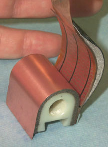 |
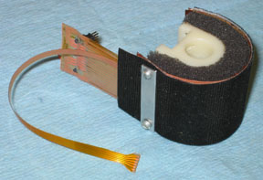
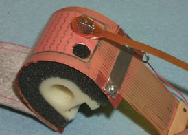
Robot Fingertip (shown with flex circuit & skin pealed back) |
|
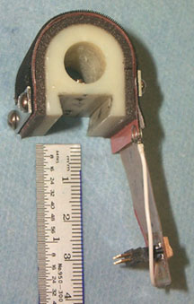 |
Completed Robot Fingertip The contact sensor is covered with microtexture 3M Greptile skin. The assembly is clampled in place using 2 small aluminum plates and 2-56 machine screws. A few coils of a steel torsion spring were used for the grounding wire clip. |
![]()
Contact Sensor Issues and Tuning
|
|
Robot Fingertip (show with flex circuit & skin pealed back) In addition to the indentations under the dielectric strips, there are indentations which run across the width of the finger (perpendicular to the former) (shown on the left). We believe these are the result of continued contact pressure on the fingertips. However, regardless of the cause these indentations are equally detrimental. These problems were corrected by using mylar backed copper foil. |
![]()
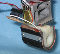
Skin Acceleration Sensor Construction
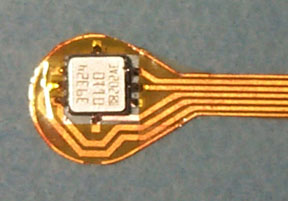
| The skin acceleration sensors are compatible with our contact location sensors and are built into the robot fingertip. Small accelerometers (Analog Devices ADXL202E) protrude through a hole in the contact sensor flex circuit and foam foundation. The accelerometer is soldered onto a mylar flex circuit. The flex circuit provides a convenient interface to signal conditioning electronics located near the robot fingertip. | 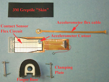 |
|
|
Accelerometer Flex Cable Mylar flex cable with Analog Devices ADXL202E soldered using low melting temperature Kester solderpaste. |
|
 |
Contact Sensor Flex Cable Flex circuit for contact sensing, compatable with skin acceleration sensor. For details of contact sensor, see above. |
|
| Transfering Hole for Accelerometer
Cutout To simplify accelerometer hole registration, the hole location is directly transfered to the copper using a pen and cutout with an exacto-knife. |
||
 |
Accelerometer Cable Next to Cutout Accelerometer shown next to cutout in contact sensor flex circuit. |
|
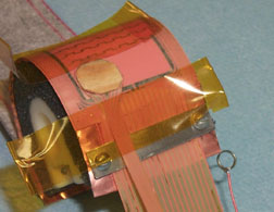 |
Accelerometer Cable Fixtured for Bonding Accelerometer cable is shown taped in place, positioned in the cutout of the contact sensor flex circuit. The region of the flex ciruit where the accelerometer lies is flat due to accelerometer packaging. A small piece of radiused wood was glued to the backside of the flex circuit over site of the accelerometer to preserve the local fingertip surface curvature. |
|
| Accelerometer Cable Bonded to Greptile skin Accelerometer cable is shown bonded to the backside of the fingertip skin. A small dot of cyanoacrylate adhesive was placed on the back of the accelerometer flex cable and the skin was conformed over the finger to maintain registration. |
||
|
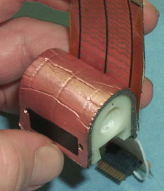
Completed Skin Acceleration Sensor Skin acceleration sensor with integral contact sensing. The tale of the accelerometer flex cable is shown in the lower left. |
![]()
| |
| |
| |
| |
| |