Overview
Real Time Trajectory Control of an Adept Robot Running
V+
Utilizing the ALTER Command
V+ Code for Real-Time Trajectory Control using an Ethernet
Interface
Velocity and
Workspace Limitation Algorithms
Problems with Ethernet Based Communication and
Velocity Based Control
| |
| |
| |
| |
| |
 The
slave-side system includes a robotic hand and arm, sensors and controller
software. The robotic hand is a designed
specifically as a test-bed for tactile sensing, grasp force control and
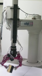
tactile exploration. The arm is an AdeptOne-MV 5-axis industrial robot
from Adept Technologies.
We have recently purchased a system to track the operatorís wrist and arm motion. The device is an ultrasonic measurement system, from Logitech, capable of tracking the 6 DOF motion of the wrist. We currently control 3 DOF of position and 1 DOF of orientation (wrist yaw) of the industrial robot arm. With this system and the software discussed below, we are capable of achieving a small motion bandwidth of approximately 20 Hz, which is sufficient for tracking human arm motion in our application.
The Adept robot is controlled by the master computer (see Overview) via an Ethernet socket connection. Commands from the master tracking system are interpreted and transformed to the robot workspace and then sent to the robot when requested.
One of the major difficulties in setting up the Adept robot as a teleoperated arm was in achieving the desired bandwidth. While the AdeptOne is a high speed, high accuracy, direct drive SCARA robot, it was primarily designed for industrial operation, such as pick and place task. Thus setting up the robot for real time trajectory following proved to be difficult.
Real Time Trajectory Control of an Adept Robot Running V+
The Adept controller software, V+, provides the front end for programming the robot. The V+ operating system is set to execute multiple program tasks utilizing time slicing with task priorities. Each system cycle runs at 62.5 Hz (every 16 ms) and is divided into sixteen 1 ms time slices. Simple motion commands can be communicated to the trajectory controller once every major system cycle. However, once a motion command, such as MOVE loc.1, is given to the trajectory controller it cannot be interrupted except in the case of an emergency stop. A single additional motion command can be queued during the first move command to ensure a smooth continuous path trajectory (the next setpoint is used to compute a new trajectory just before the original deceleration phase was to begin).
While this creates smooth motion for a string of predetermined setpoints this is not the case for continuously updated points. Why, you may ask? The robot has certain velocity and acceleration limits set by the programmer and these limits are used by the trajectory controller to create the specified trajectory profile. The robot attempts to get to each point as fast as possible given the limits. Thus to achieve reasonable motion bandwidth, the limits must be fairly high. However, if the motion is relatively slow the robot could reach the desired setpoint before the next setpoint can be used to create a continuous path, thus giving you high acceleration stops and starts.
The ALTER command provides a solution to the problems described above. To access the ALTER command, your Adept system must have the Enhanced Trajectory Control License and running V+ version 12.4 or later. Updating the V+ operating system is no easy task, however Adept technical support group provided me with excellent help.
The ALTER command allows the user to specify a real-time path modification that is applied to the robot path during the next trajectory generation computation. Using this command the programmer is now responsible for creating a smooth trajectory but can count on the path modifications being performed at each major servo cycle (every 16 ms). Thus in using this command the programmer is now essentially sending a velocity command to the robot (relative position changes). However, there are a few caveats... (1) This command essentially by-passes all the path planning software. Thus you could attempt a very large move, say 50 mm, and it will attempt to complete this move with in one servo cycle (16 ms). I have not actually tried this but I am told that the robot will shut down. (2) The documentation is fairly limited and, while the tech support staff is extremely helpful, this is not a command commonly used in industry thus their experience with it is limited. (3) The command values for X-Y-Z path modification is straight forward; simply indicate the translation to be performed over the next servo cycle in millimeters. However, the rotational path modification values are quite a bit more complicated. For an in depth look at this see the following paper: Sensor Networked Based Workcell for Industrial Robots by Y.Liu et al.
V+ Code for Real-Time Trajectory Control using an Ethernet Interface
The program task structure to utilize the ALTER command as well as the TCP/IP interface is a bit unique. This section will detail the program tasks and a link to code that I am currently using.
To control the robot using commands from the socket connection and using the ALTER command requires three separate task. The program with the highest priority, task level 0, runs the ALTER command loop. At task level 1, the TCP/IP ethernet interface is running. The program is the bulk of the code and receives the commands from the master computer, ensures that they are correct and with in the workspace limits. At a slightly lower priority, task level 2, the MOVES HERE command is called once and then the ALTER command can then begin (this is somewhat confusing but it is require to use the ALTER command).
Velocity and Workspace Limitation Algorithms
One important aspect of the task level 1 program code is the modification of the data to implement both velocity and workspace limitations. Since the master computer sends the relative position changes to be executed at each servo cycle, the program can simply limit the magnitude of the position change and thus the robot velocity. However, to ensure proper position tracking between the slave and master, the overflow position values must be stored and executed at a later time. This following pseudo code demonstrates how this is implemented:
The variables:
des_step - desired relative position
change for the next servo cycle
stored - overflow position changes
delta_max - the maximum relative
position change (max velocity * 16ms)
step - value actually sent to ALTER
command
stored = stored + des_step
if stored >= 0 then
step = min(delta_max, stored)
else
step = max(-delta_max, stored)
end
stored = stored - step
ALTER (step)
This method of velocity limitation allows for proper position tracking in a relatively simple manner.
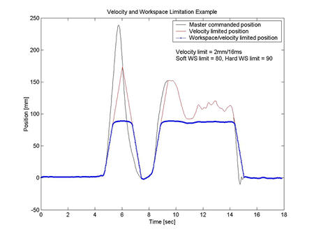
To limit the workspace of the teleoperated robot one could simply set the delta_max term to zero when the limits are reached. However this would lead to abrupt stops and starts of the robot at the workspace boundary. To ensure smooth motion, a nonlinear mapping method is used to modify the desired position near the boundaries. Near the boundaries an asymptotic function based on 1/x is used. The figure below shows an example of the velocity and workspace limiting for a given user motion in on axis.

Here, V+ code for real-time trajectory code, you will find a posting of the V+ code I used to implement the ALTER command and velocity limiting. Please note: This code is only posted as a aid for other programmers for development. The programmer assumes all risks and by downloading the code agrees that under no circumstances to hold the authors of this website liable for anything resulting from using this code.
Problems with Ethernet Based Communication and Velocity Based Control
Even with implementing the above ALTER based trajectory control the motion of the Adept was disappointingly jerky. The main source of this problem was traced to unevenly spaced sampling.
The basic communication framework is set up as follows. The Adept runs the TCP/IP communication loop every 16ms (the 62.5 Hz base servo cycle). Each time through the loop the Adept sends the master computer a character to indicate that it is ready to receive the latest data (i.e., the latest change in relative position or delta). One the master side, a process is running that waits for the ping from the Adept and then looks into shared memory for the latest position. The relative position change is computed and then sent to the Adept over the socket connection. However, this leads to a very interesting problem...
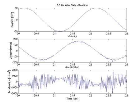
Even though the Adept loop is running at exactly 62.5Hz, the communication with the master can vary by a very small amount. This means that the master loop is only running at an average of 62.5 Hz but can vary slightly with each loop (approximately +/- 3 ms). Thus the master is not sampling the data every 16 ms resulting in unevenly space sampling. Suppose you create a smooth sine wave position command. If the sine wave is sampled at regular intervals then each of the derivatives will be smooth. However, if it is not sampled at regular intervals the velocity and, more importantly, the acceleration will not be smooth. The plot below was created with recorded data from the Adept robot. As you can see the acceleration is not smooth which resulted in noticeably shaky motion.

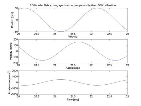
To solve this problem, a sample and hold routine was implemented on the master side. Based off of the first few requests from the Adept, the master computer begins to shift the time in which the data to shared memory is uploaded for the communication process. In this way, the master computer only updates the data when then it is sure that the Adept will not be requesting data at about the same time. Thus the data from the tracker is delayed approximately 8 ms The implementation if this synchronization results is smooth motion on the Adept robot with a small cost in latency. The plot below was created using the algorithm discussed above.
