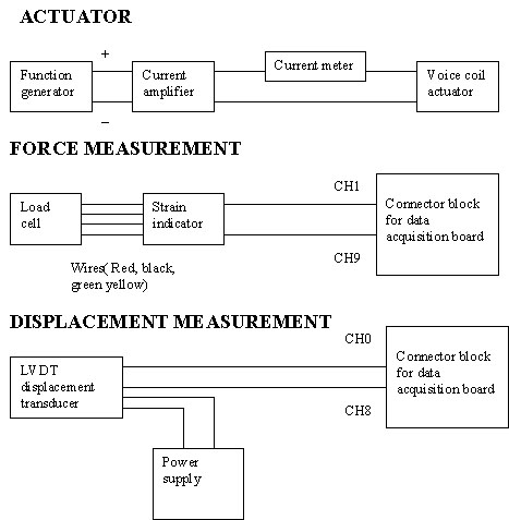
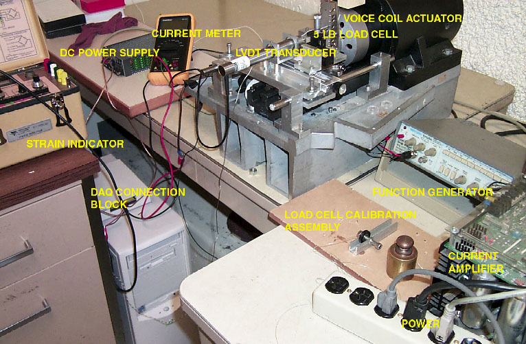
During operation of the test machine, the function generator produces an input voltage signal that is fed into a voltage-to-current amplifier. The current from the amplifier drives the voice coil actuator. Thus, the net result is the function generator directly controls the force (not displacement) generated by the test machine. A multimeter monitors the current into the actuator.
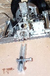
The outputs from the machine are the displacement of the actuator (and sample if that is loaded into the machine) and the forces associated with this displacement. These outputs are measured by an LVDT and a load cell/strain gauge and fed into the computer via a NI DAQ card and a program written in LabView.
|
General Setup
|
Turn on power strip, computer, etc. Make sure that the voltage-to-current amplifier is not connected. Otherwise, the actuator may move suddenly. |
|
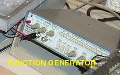
Function Generator
. |
The signal generator is the input to the system.
It controls the force output of the actuator.
|
|
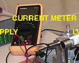
Multi-Meter
|
The multi-meter is used to monitor the current
out of the voltage-to-current amplifier and to ensure that the bias (offset)
current out of the amplifier is zero.
|
|
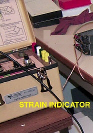
Strain Indicator
|
The strain indicator is used to read the output
of the load cell/strain gauge. It is hooked up as a full-bridge.
|
|
Software
|
The software is written in Labview. It
takes readings from the strain gauge/load cell and the LVDT to monitor
the displacement and forces associated with sample deformation.
|
|
Calibration
|
It is assumed that hte displacement and the
force readings are linear. This means that the equations used to
describe them are:
displacement = a1(voltage_displacement) + b1
|
Last updated February 27, 2000 by chengw@stanford.edu.
Email all biomimetics personnel biomimetics@cdr.stanford.edu.
Email Stanford biomimetics personnel biomim-local@cdr.stanford.edu.