Notes on Embedded Pressure Sensor
Jorge Cham - August 11th, 1998
Design
Figure 1. Circuit board design for surface mount commercial pressure sensor and instrumentational amplifier with voltage divider.
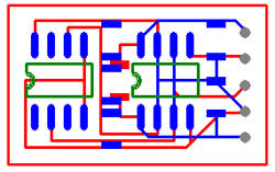
The general function and shape of the part is designed. General strategies are formulated for build order (which can only come from experience?), how to get the electrical leads out of the part (if any), how to free mechanical linkages like joints, etc.
The embedded components are designed or selected and "prepared" for embedding. This involves the addition of fixtures, part or sacrificial material and even some pre-assembly. In our case, Urethane is the part material and red wax is the sacrificial material.
Figure 2. Design using Mike Binnard's AutoCAD ARX plug-in. Blue is the part "primitive" and pink is the embedded circuit "primitive"
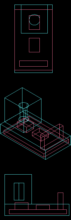
The models for part and embedded components are created from primitives, which are subsequently merged, substracted or converted to "embedded component".
The model for the circuit board (pink) only contains dimensions for the board, the sensor, the amplifier and the leads (tall, wide block), which are surrounded by sacrificial material (red wax in this case).
Uncertainties in the embedded components must be accounted for in the model. For example, the board manufacturer cut the board perimeter very poorly, with variations up to .050 in. Also, the solder that bonds the circuit elements will result in variations in the position and height of these elements.
Note that these effects can be severe, especially in tight-tolerance designs in which the embedded component must be placed accurately. For example, note that a misplaced circuit board may cause the sensor port to be misaligned with the air chamber, or it may cause one of the embedded components to be damaged by the mill in subsequent steps.
Note the space between the pressure sensor (the larger of the two blocks on the circuit - refer to the side view at the bottom of the figure) and the hollow chamber. During the process, a drop of wax was placed on top of the sensor's port so that, when the wax is later removed, there is a clear path between the chamber and the sensor port. Although the sensor could have been modeled with this sacrificial material going up to the chamber, it seems that it is sometimes necessary to add extra sacrificial material to ensure that volumes of sacrificial material created inside a part are not trapped due to errors in positioning.
Figure 3. Compacts list. The plug-in orders and simplifies (some issues still need to be resolved) the embedded component (yellow),part (red) and support (green) compacts.
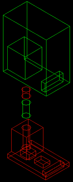
There are multiple ways to simplify (merge and maintain the order of) the compacts (currently, the plug-in presents an order which depends on the order the primitives were merged. A more flexible algorithm is being developed). The "best" solution will depend on the number of times the materials are poured, simplicity, and whether or not it is even possible or advisable given the tolerances (for example, can you afford to have the mill pass so close to a fragile embedded components when there is uncertainty in its position?).
Sometimes, as was the case with this part, it is possible for the algorithm to suggest build orders that are completely different than what the designer had in mind. Redesign or readjustments may be needed. Familiarity with the algorithm will influence the designer's expectations.
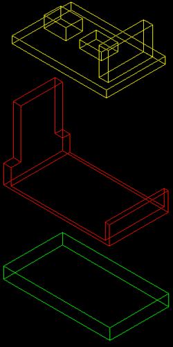
Figure 4. Single Step Geometry models
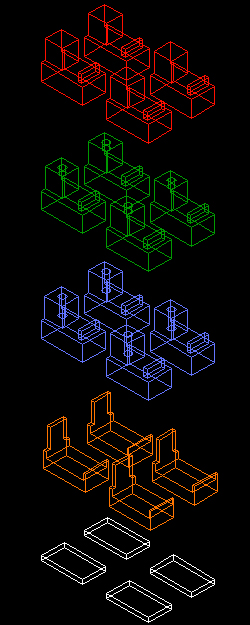
The Single-Step Geometry (SSG) models (SSG00X.sat) are generated by the plug-in as well as the run files (SSG00x.run). In general, the SSG's are the surfaces that must be milled after each pouring of material.
The planner (sdmplan) then generates the CNC files from these. These CNC files are verified with spath.
Following are specific notes for running these programs.
Directory schematic:
- DB (contains RPL machine files)
- Part Directory
- model (contains the SSG00X.sat files)
- CNC (will contain the planned CNC files)
- cutters.nc
- spath SSG00X_X_X_2DX.cnc
- contains run files
- sdmplan SSG00X.run
File nomenclature:
SSG00(X1)_(X2)_(X3)_2D(X4)
X1 - SSG number
X2 - layer of SSG (there will be one between every pair of z-heights)
X3 - nothing important
X4 - cutter used (for this example, 1 was 1/4" endmill, 2 was 1/8")
The SSG00(X1)_(X2)_(X3)_0_Mow.cnc files will remove the surrounding material for each layer. The _2D(X4) files will simply trace the outlines of each feature. If the cutter used in one of the _2D(X4) files is the same as the cutter used in the Mow file, it is redundant.
Manufacture
Figure 5. Jay, Jorge and Mike at the Haas CNC machine.
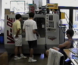
The CNC files created by the Berkeley-Stanford sdmplan software are downloaded into the HAAS.
For each SSG, the CNC code for each layer must be executed in descending order.
Figure 6. The second Single-Step-Geometry
The first Single-Step Geometry was carved out of the substrate (blue wax) and then Urethane was poured. The figure shows the second SSG (compare to SSG's in figure 4).
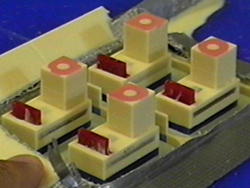
Figure 7. The prepared boards are placed at the appropriate step in the process.
One of the boards did not fit properly in the cavity due to poor cutting of the board's perimeter. The appropriate way to fixture the embedded components depends on the tolerances of the components. For example, if there are uncertainties in the board perimeter, then placing them in a cavity is not the best solution. A better solution might be to include holes in the board design and create nubs or cylinders on the surface.
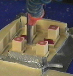
Figure 8. Urethane is poured over the embedded circuit boards.
Urethane Hardener and Resin are mixed (equal amounts per weight) and poured. The entire palette is then placed in a vacuum chamber to help eliminate air pockets or bubbles.
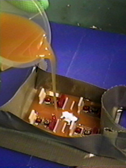
Figure 9. Sacrificial material(red wax)is poured into the chamber.

All the files that are generated by the above process can be used (in the appropriate sequence). However, knowledge of the intended build process can allow the manufacturer to select which CNC files are executed to save on time and effort. For example, after the hole is made for the chamber with the first layer, the rest of the files for this SSG (shown in figure 9) are not necessary.
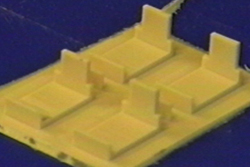
Figure 10. Final milling.
When the final milling is done, the only thing that holds the part to the blue wax substrate is whatever bond the poured plastic made with the substrate. In this case, the Urethane does not stick well to the blue wax. When the mill removed the last of the material that anchored the part, the air jets from the coolant tubes blew the part away. To resolve this, the coolant was turned off right before the final cuts.
Figure 11. End Product.
Again, the unnecessary remaining CNC files can be ignored. In this case, once the parts could be removed, the rest of the of Urethane did not need to be machined away.
Figure 12. Post-processing.
The through-hole (seen in the figure) is drilled into the finished part.
Bioact solvent heated to above 70 degrees Celsius (approximately the melting temperature of red wax) is used the remove the sacrificial material.
The threads in the through hole are tapped.
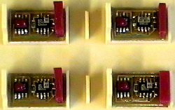
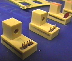
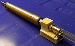
Figure 13. Additional components.
The additional components and final system is assembled. The leads were bent and extended.
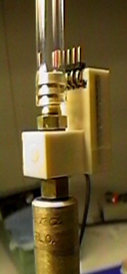
Figure 14. Sensor on pneumatic cylinder.
The circuits now remain to be tested. However, since the circuit boards were not thoroughly tested in operating conditions before the SDM process, it will be difficult to characterize its effects. Some possible effects: Stresses in the plastic surrounding the circuit due to shrinkage may damage connections in the boards. Temperatures or vibrations in the process may damage some components.