Notes on a Linkage with Embedded Motors
Jorge Cham - September 15th, 1998
(for an overview of the design and manufacturing process used here, see Notes on Embedded Sensor in the documents page)
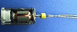
Figure 1. Motor (6mm diameter) used for vibration in pagers (beepers). Figure shows a dissected motor with the cable transmission attached.
![]()
Small (6mm diameter, $2 each) motors were used to actuate a pin joint linkage. The motors and their electrical connectors were embedded inside one of the links. Hollow channels for the cable transmission were also created inside the link.
Specifications for the pager motors were not available. Similar pager motors from MicroMo specify only armature resistance (+-12%), no-load speed (+-25%) and no-load current (+-50%).
Figure 2. Transmission vs. Strain (%) for the cable transmission used.
![]()
The transmission used to actuate the joint consisted of attaching Spectra 2000 (by Allied Signal) synthetic fiber to the motor shaft. As the motor spins, the cable coils and shortens under a load. Torque and rotational motion are transmitted into linear force and motion.
Some modeling was done and some experimental results are shown in Figure 2. The vertical axis shows some measure of the transmission (motor torque or current divided by the load force). The horizontal axis shows the linear strain in percentage. As the cable coils, the mechanical advantage decreases. This transmission is similar to the LADD transmission developed for the Utah Arm by S. C. Jacobsen and further investigated by Pottebaum and Beaman (1983) and Mennitto and Buehler (1995 and 1997).
Figure 3. Figure shows the motor and the spacer that was manufactured to embed the motor.
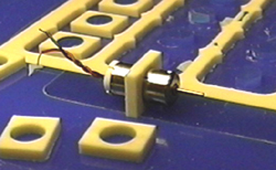
To place the motors, and as part of the embedding technique used, the spacers shown in Figure 3 were designed and manufactured with the same process.
Figure 4. Cross-sectional (top) view of the design of the linkage. The schematic shows the embedded components (in teal and purple).
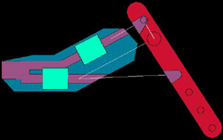
The linkage was designed in AutoCAD. The placement of the motors and the range of motion were designed to linearize to a certain extent the non-linear transmission shown above.
Figure 5. View of the embedded components (teal and purple) inside the link design.
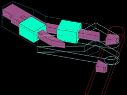
The embedding technique for the motors consisted of modeling a large box (teal color) that surrounds the motor and spacer. These boxes and the channels for the electrical connectors and cable transmission (purple color) are then merged (as 'embedded components') inside the link design.
The idea is that when the planning algorithms create a pocket for this box, the motor and spacer are to be placed inside of it.
Figure 6. AutoCAD model of the link design.
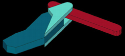
Once the motor and spacer are placed inside the pocket, part material (urethane) is poured on one side of the spacer (thereby embedding the back half of the motor). Sacrificial material is poured on the other side (thereby encapsulating the shaft and cable). This will be illustrated later.
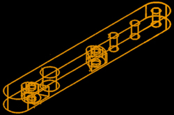
Figure 7. AutoCAD model of the link design (top view).

Figure 8. AutoCAD model of link 2.
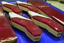
Figures 8 and 9 show the AutoCAD design of link 2 and the finished part before removing the sacrificial material (red wax). Nylon bearings are pressed unto both sides of the larger hole.
Figure 9. Manufactured link 2. Red wax was used as the sacrificial material.
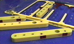
Figure 10. Single-step geometry of link 1 at the point in which the motors are embedded
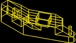
Figure 11. Single-step geometry shown in Figure 10 with the motors and electrical connections embedded.
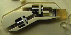
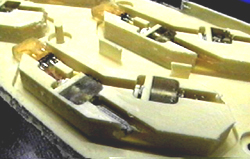
Figure 12. Close-up of embedded motors. The leads (shown bottom left) were encased in the sacrificial material (in this case, soap).
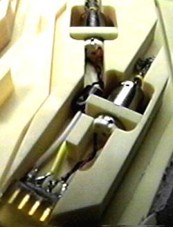
Figure 13. The cable used in the motor transmission was tucked into the channel.
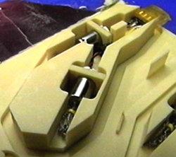
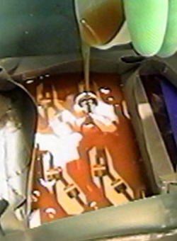
Figure 14. The sacrificial material was poured, planed and the next Single-step geometry was machined. Note that the motor shaft and cable are now encased in the sacrificial material.
The sacrificial material (soap, amber color) was poured (melting point approx. 70deg. Celsius) on one side of the spacer, encapsulating the motor shaft and the cables. The soap was then planed off and machined. The soap was acceptably machinable at very low feed rates, though it left the entire palette covered in soft soap 'chips'.
The other side of the spacer and the channels including the wiring were left empty. These were covered in Urethane in the subsequent step.
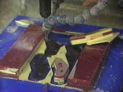
Figure 15. Urethane is poured over the embedded motors.
Lesson learned: Urethane reacts badly with moisture. The soap was poured and machined but left over-night before the Urethane was poured over it and moisture is believed to have collected or diffused on the soap at this time. As the Urethane cured, bubbles could be seen coming out of the areas where the soap was. The moisture caused the plastic directly on top of the soap to have a very porous appearance. Though the presence of moisture is known to ruin an entire pouring of Urethane, in this case the critical areas had acceptable hardness.
Figure 16. Final stages of machining. Figure shows one of the parts detaching before it is completed.
Due to the poor bonding between the Urethane and the plastic, some of the parts flew off along with the surrounding plastic before the mill finished cutting them out. Some techniques to avoid this include creating 'anchors' so that the layer of Urethane extends into the wax at some non-critical points, lowering feed rates and turning of cooling jets.
Figure 17. Link 1 finished. Note the different layers and materials used.
The red wax seen in Figure 17 was removed manually and the soap was removed with hot water.
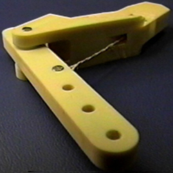
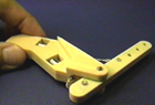
Figure 18. Finished linkage with sacrificial materials (red wax and soap) removed, cleaned and assembled.
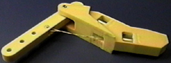
Figure 19. Finished link.
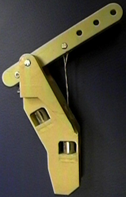
Figure 20. Finished link.