Overview
Steps:
(1) Export Single Step Geometry (SSG) model from solid modeler
(2) Load part into UniGraphics
(3) For each operation specify:
A. Operation type(4) Create Multiple Copies (if desired)
B. Part Geometry
C. Tool
D. Drive Method
E. Cutting Parameters
F. Non-cutting parameters
G. Feed Rates
(1) Export Model from CAD
Create a solid block with negative of part to be produce. Make sure there is one part for each stage or layer of SDM process. Use either the compact generation in AutoCAD or do it manually in some other solid modeler. In any case the model should have a cavity for all of the geometry that needs to be machined at this time.
The Coordinate System of part should be in a logical position
(e.g. a corner of the block)
and relative to a single coordinate system.
If making multiple parts simultaneously minimize unused space between
parts.
Leave enough room between parts for a removal profile cut. Probably
at least 1/8, or ¼
Be aware of tool sizes and flute lengths for small parts. (1/2
to 1/26)
Export model as a STEP x03 file. In AutoCAD use the "stepout" function. In Solid Works, use the "Save As" function.
FTP files to Maximo
Make sure the part extension is .stp
This may well entail changing it in UNIX from ".step"
to ".stp".
Create a folder for each part
Create a sub-folder for each SSG. Each folder will eventually
contain 3 files for each tool size and cut. (.cnc .cls. and .ptp) as well
as a ".prt" file for each UG part you create.
<<Figure of File Structure>>
(2) Load part into UG
On a UNIX workstation, telnet into Maximo.
Type UG at the prompt.
In window that appears select version 15 by entering 1, then press
the Apply button.
This loads the main window, which may take a moment.
Depending on your system set ups you many need to:
Press "1" to start UG
Set "xhost +" on your local machine
From main window select: File-> New
This brings up the <New Part File> window..From main window select: File -> Import
Change the part units to MM !!!
Double click the proper part sub-directory
In the selection field append the new name for the part.
Press OK or Enter to continue.
Select Step 203Note: when red light is showing in top-left corner of graphics window, the system is thinking. The green light indicates it is waiting from input from the user.
Click Choose Part 21 file button
Select the appropriate .stp file, press OK, or Enter.
Press OK
Be Patient!
From main window select: Application -> manufacturing
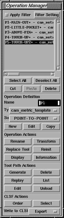
Managing Operations:
There should be a large box at the top of the manufacturing window, this is as scrolling list of all the operations you have already defined. It is initially empty. An operation should be created for each combination of depth, tool size, and distinct geometrical area.
The list of operations can be selected to modify, rename, move, or delete. The buttons below the list operate on elements of the list that are highlighted.
Managing windows:
Each application, function, and many sub-functions will have their own window. Generally windows should be navigated from the top down. For this tutorial each window will be treated separately. Only the applicable fields will be mentioned, but in each case they will be from the current window starting from the top. When entering a new window its title will be indicated with the following format: <window title>
Graphical View manipulation:
Right mouse button brings up a menu with view options such as:
Zoom (also F6)How to change Coordinate Systems:
Rotate (also F7)
Fit (also Ctr-F)
Half Screen
Orient View -> ISO <- Try this now.
Before defining (and definitely before generating) an operation, make sure the CS is in a logical position. This will probably be z = 0 on the top surface of the part, and x = 0, y = 0 at the bottom right corner of the top surface.
There is as WCS (World Coordinate System) and a MCS (Manufacturing Coordinate System. Make sure to change both.
From main window select: WCS/ -> WCS Origin
This brings up the
<point Subfunction> window
Default selection method is control point. Select a point by graphically picking. The line to be chosen will highlight. The point selected will be either the midpoint or end point on that line closest to the point of selection. If you selection looks good, press OK and then BACKRepeat for the MCS in WCS/ -> MCS Origin
(3) Operation Definition:
Each operation has minimum of 7 steps (list below as A G) needed to define the operation, these are listed below in order of definition.
A. Operation typeOnce these 7 steps have been completed there is sufficient information for UG to create tool paths.At this point you should be in the <Operation Manager> Window
To define a new operation:
Fill in the new name text box in the middle of the window. (the default value is P1)
Try a descriptive or ordered nameSelect type of operation:
Pull down menu (default value is POINT-TO-POINT)
Select either planer mill or Fixed Contour
The operation described below is Fixed Contour.
Select it.Press the New button to enter the definition window
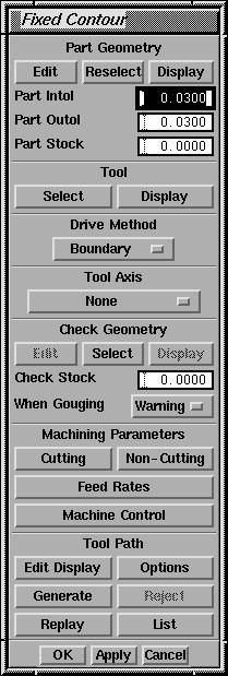
At this point you should be in the <Fixed Contour> window.B. Part Geometry
Under the Part Geometry heading press the Select button.
This brings up the <Part Geometry> window.Press the diamond radio button Geometry (the default value is Features)C. ToolPull down the Methods menu (the default value is Surface Regions)
Select Faces (or curves, or faces + Curves)
Select the smallest area that will enclose at least the entire are to be cut with this
operation. A depressed face may be the simples, e.g. the base.If highlighted area is correct, press Accept and then OK to exit the <Part Geometry> window.
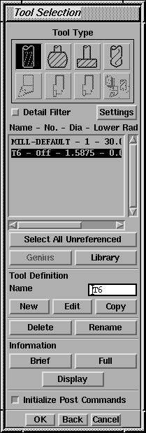
Under the tool heading press the Select button
This brings up the <Tool Selection> windowFill in the name of the Tool. Refer to the table. [e.g. T4 for ¼ flat]Table of Standard HAAS tools
Press the New button
Enter the Diameter, Length, and Flute length (in MM !!!) (25.4mm = 1 in)
Press OK
Make sure the proper tool is highlighted and press OKTable accurate as of 11/16/99
Tool # Type Length Flute Length 3 1/2" Flat 2.85" 2.00" 4 1/4" Flat 1.30" 1.00" 5 1/8" Flat 2.00" 1.00" 6 1/16" Flat 0.40" 0.30" 7 1/32" Flat XX XX 8 1/2" Ball 2.85" 2.00" 9 1/4" Ball 2.20" 1.50" 10 1/8" Ball 2.00" 1.00" 11 1/16" Ball 0.40" 0.30" 12 1/32" Ball 0.20" 0.15"
As a shortcut or check try running Jainpeng's program, which pre-loads his defaultsPressing the Display button under the tool heading will give a visual check as to the size of the tool.
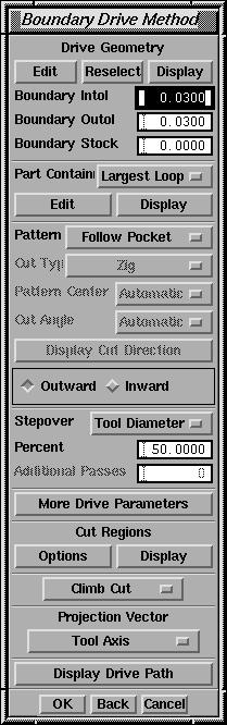
D. Drive Method
Select the Boundary pull down menu and release (Boundary is the default, and that is the option we want to redefine).
Inside the <Boundary Drive Method> window:Press the Select button by the Drive Geometry option:Back inside the <Boundary Drive Method> window:
Inside the <Boundary Geometry> window:Change the mode pull down menu from Boundary (the default) to either Curves/Edges (or face)Click OK
Select the appropriate geometry. (a continuous loop of edges or a submerged face)
Press OK to exit <Boundary Geometry>For Face:
For Face:
Material retained Outside
Ignore holes
Dont ignore islands
For Curves:
be careful selecting, use quarry
select if ambiguous. Feel free to rotate
the view. In selection mode, the middle mouse button = AcceptClick OK when done
Change the Pattern pull-down menu to Follow Pocket (or Profile, default is Parallel lines)If using Follow Pocket change radio button from Inward to OutwardIf there are islands in the geometry, click on More Drive Parameters
Check the Island Cleanup box. (also Wall Cleanup if that is a concern)
Click OKClick OK to exit <Boundary Drive Method> window
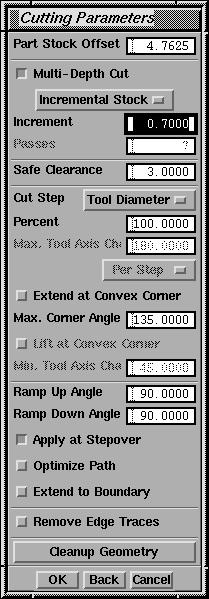
E. Cutting Parameters
Press the Cutting button under Machining Parameters to enter the <Cutting Parameters> window:
Enter value for Part Stock Offset This is the depth of cut, or the distance from z = 0, to the face selected for cutting, in MM !!F. Non-cutting parametersCheck the Multi-depth Cut box
Enter value of Increment. For ¼ end mill--1.2mm; for 1/16 end mill --.7 mm
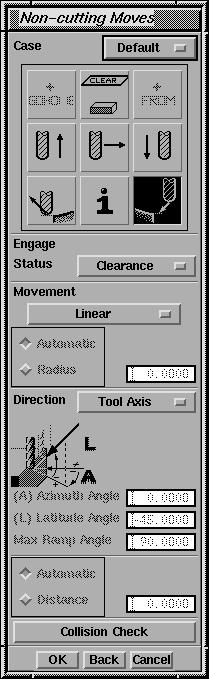
Click OK to exit <Cutting Parameters> window.Press Non-Cutting button for the <Non-Cutting Moves> window.
Of the 9 icons in the top box, the lower right should be highlighted by default, this is the engage option.Click on the Engage Status pull down menu and change from Manual (the default) to Clearance
Note: the cutting plane is the plane to which the tool retracts between cuts. Is should be safely above any protruding geometry on the pallet.
Click on the clearance plane button (top row, middle button)
In the <Clearance Geometry> window:Click on the dashed triangle button to create a new cutting planeNote: once established a cutting plane is difficult to remove. Do it right, or start the operation over.
In the Offset text box enter: 10 (millimeters--as a minimum).
A triangle should appear 10 mm above the CS along the Z-axis.
If this is a safe plane for the end mill to move in, then:
Press the Accept button
Press the Return Current button at the top of the window.Click the center (of the 9) button [Transverse]
Click OKClick OK to leave the <Non-Cutting Moves> window
G. Feed Rates
Cut is the only rate that has to be changed. For blue wax and a 1/16 bit, 400 is an ok rate. For other combinations of tools and materials, check with Tom. . .
Pressing the Generate button creates the paths, and provides a brief visual check to see if they were created and if they look good. There should be several layers of blue curves on top of each other that nicely trace out the geometry to be cut. If everything looks in order,
Press OK to define the operation and return to the <operations
Manger> window
(4) Creating Multiple Copies (if desired)
Once the tool paths have been created it is relatively easy to create duplicates or mirror images of the tools paths, with arbitrary offsets. Two of the most useful of the transformation tools are the rectangular array and the mirror functions. These two will be described below
Select all of the operations to be copied. Once they are all highlight (using shift or ctr. button when selecting), press the Transform button to initiate the duplication.
Select the appropriate tool from the list that appears.
For Rectangular Array:(5) Post Process/convert to CNC formatChoose a base (or control) point from which to define the array of copies.
A corner (on the top surface) of the part is a logical place for the base point. It should be on a an outside corner of the entire array. Select the point by clicking near the end point of a line. The line with highlight when the cursor is near, and the point will be at the end or mid-point closest to the location of the cursor when the mouse button is pressed.If the point is acceptable, press OK.From the off set window that appears choose the number of rows and columns of the array, and how much each should be offset.
DXC and DYC are the distances for the offset from the base point Make sure these are large enough so the tool paths do not overlap.Choose CopyColumns and rows are the number of each. Make sure an integer number is inputted. The X and Y directions correspond to the CS.
If ok, choose Accept (try using half size and the pan functions to help with a visual verification of the array)
To instantiate the copes in the list of operations press the Paste button in the operation manager. Each element in the array will be a separate operation with a default name. Note that the new operations will be inserted after the currently highlighted operations, and the original paths will still exist under their original names.
Mirror Through Line
Select a line option (existing line is easiest).
Graphically pick line of choice.
Choose Copy
Press OK
If copy is acceptable click OK
Press Paste to instantiate the mirrored copy.
Select all operations with the same tool size
Under Write to CLSF Click and release pull down menu (default value
is Export)
Choose a name for the tool path. Something related to order, geometry, and/or tool size.Press OK to create a CLSF file (.cls)
The default is the part name, but since any part will have multiple cuts, a logical system for naming should be used.
Select Toolbox -> CLSF (or Ctrl+Alt+C)
Select the .cls file you just created.At this point there are 4 things to modify:
Press OK
In <CLSF Manager> window:
Select all the processes.
Press the Post Process button.
(1) Make sure the Input file name is correct (only defaults correctly the first time)This creates a .ptp file
(2) Specify MDF name. Choose : /users/hasler/haas2.mdfa
(3) Listing output, set pull down menu to None
(4) Press Post Process
Conversion from .ptp to .cnc
In the editor of your choice on maximo:
Delete the 2nd and 3rd lines (NG 21; NG 90)
Add the file header.cnc after the first line (which contains only %)
Change the tool number:
T5 -> Txx
H5 -> Hxx
Where xx is the tool number you are using.Add the file footer.cnc at the end of the file
Change 2nd to last line to M02 from M30 if the program is not to be left in the HAAS memory
Save file with a ".cnc" extension