Compliant SDM Leg
| Manufacture
of a Double-Jointed,
Compliant SDM Leg |
|
0. Leg Description
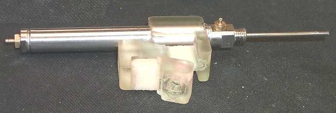
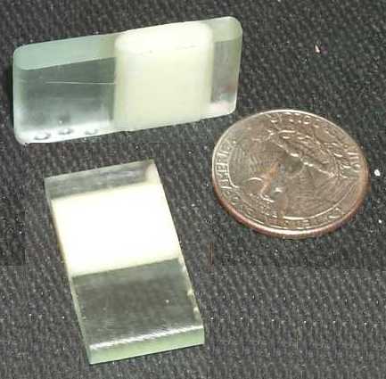
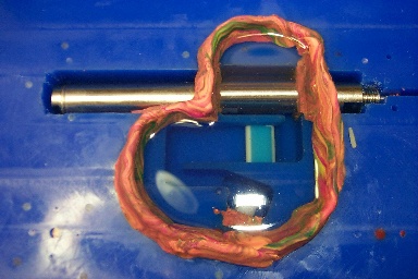
| Completed Leg
|
This SDM'ed leg is designed for a hexapod that incorporates
the ideas of sprawled posture and compliance. The leg combines two
different urethanes - Innovative Polymer's clear, stiffer 70DC and cream-colored,
softer 90A - to form rigid links and bendable joints. The leg is
designed to be compliant mainly in the two directions shown, although it
is also compliant in the approximate DOF of rotation about an axis parallel
to the piston axis.
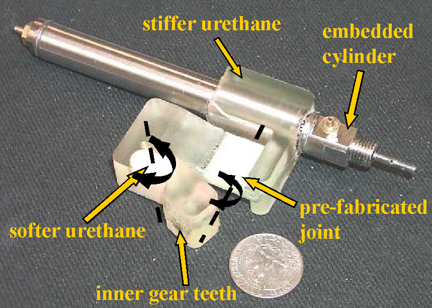
The completed leg includes an embedded Airpel E9 piston, an embedded pre-fabricated flexible joint/flexure, a non-prefabricated flexible joint, and inner gear teeth cast to match the output of a Hi-Tech 500BB servomotor. The inner gear teeth was formed via the partial embedding and removal of a custom gear assembly. The fabrication process involved two pours of 70DC, two pours of 90A, and seven separate CNC cuts. |
I. Manufacture of the Embedded Flexure Joint
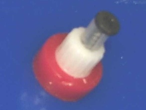
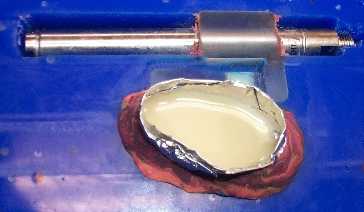
Example Flexure
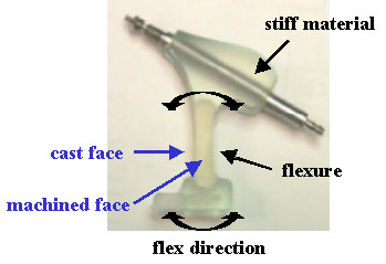 |
Prior experience with 90A has shown that it is too soft
to be machined via conventional methods. An exception is facing off
the top of a 90A pour that is constrained on all sides by wax or stiffer
urethane. Even though this facing operation introduces imperfections
and defects into the machined surface, this is acceptable when the machined
face is affected minimally during bending.
For example, this flexure consists of the cream-colored 90A surrounded by the clear 70DC. In this case, the faces on the left and right sides of the flexure undergo maximum deformation during bending and should not be machined. In contrast, the top face can be machined. |
| This machining constraint, along with a nonvarying build direction
imposed by the pallete and the CNC mill used during the SDM process, mean
that the faces of the pre-fabricated joint that undergo maximum-deformation
faces are orthogonal to the build direction. Faces orthogonal to
the build direction are usually machined during the SDM fabrication process.
To avoid machining these faces, the flexure was pre-fabricated and embedded within a 70DC pour during leg manufacture. The flexure conisted of both the 90A joint and supporting 70DC material. An earlier attempt involving a pre-fabricated flexure of only the 90A failed; although curing 90A bonds well to cured 70DC, curing 70DC does not bond well to cured 90A. A SDM urethane pouring tutorial can be found here. A presentation containing additional information about urethane pouring can be found here. |
Pre-fabricated Flexures
 |
II. Preparation of Embedded Parts
|
Embedded parts require advanced preparation prior to the leg manufacture.
In this case, this involved cleaning the piston surface to increase bonding
strength, covering the cast faces of the embedded flexure with tape, and
assembling the gear structure.
The gear structure was composed of wax, a Hi-Tech 500BB inner gear, tubing, and a screw. The gear assembly was a positive around which urethane is cast. It was only partially embedded in the leg, and was removed from the completed leg. |
III. Machining of Initial Cavity and Placement
of Embedded Part
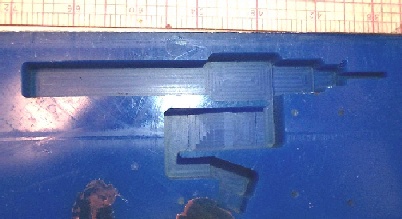
Initial Cavity The leg and machining operations were designed in Solidworks and exported to Unigraphics for tool path planning. The actual machining utilized the HAAS, a 3D CNC mill. Machined surfaces provided features useful for the alignment and placement of embedded parts. |
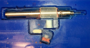
Embedded Components
 |
IV. Initial Pour of 70DC
After placement of the embedded components, the cavity was filled with
70DC. An intentional 'over-pour' meant that most bubbles, foreign
materials, and other imperfections could be removed by facing off the top
surface..
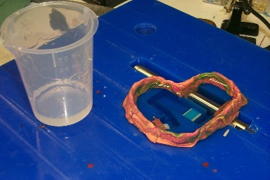 
Pour of 70DC |
V. Forming the Other Flexure
Pour of 90A |
The non-prefabricated joint was fabricated entirely during the main process of leg manufacture. Some 70DC cast during the initial pour was machined away to form a mold for the 90A. The 90A was also overpoured. |
VI. Final Shaping and Extraction
|
Two additional CNC cuts were necessary to finish
the leg. One imparted the final shape to the urethane portion of
the leg; the other was a cut-around the completed. The cut-around
faciliated the removal of the completed leg from the wax bed.
|
VII. Notes