PROPOSAL BAA 95-37 Volume I
Title: Design Space Colonization
Duration: three (3) years
Business Types: Educational
Prime Contractor: Stanford University
Contact: Mark Cutkosky
Center for Design Research
560 Panama Street
Stanford, California 94305-2232
voice: (415) 725-1588
fax: (415) 725-8475
e-mail: cutkosky@cdr.stanford.edu
Administrative Contact: Ruth Kaempf
Senior Contract Officer
Sponsored Projects Office
857 Serra St., Rm. 260
Stanford University
Stanford, CA 94305-4125
voice: (415) 723-4740
fax: (415) 723-1654
e-mail: as.rmk@forsythe.stanford.edu
Subcontractors: Option-1: Pipeline Systems Analysis
(B)Executive Summary
Political, economic and technological forces are changing the
landscape of engineering. There is an increasing need for
organizations to form joint design and manufacturing teams that
collaborate for the life of a project and then disperse. These teams
need to quickly locate, evaluate and make effective use of the best
resources (tools, facilities, people) available, wherever they may be
found. In this proposal we concentrate on a subset of this problem
that is most critical in the early stages of developing a product,
when new ideas, processes, components and materials are being explored
and prototypes are developed. We propose solutions that will enhance
the ability of teams to exploit novel tools and processes for
improving product performance and reducing costs, and to document
their explorations for others to follow. In this way we believe that
the slow cycle of exploration, maturation and widespread adoption that
typically accompanies significant advances in materials and processing
capabilities can be compressed from decades to years.
Innovative Ideas
Design Space Colonization (DSC) is the
component of the Palo Alto Collaborative Engineering (PACE) effort,
consisting of CDR, EIT, KSL, and Lockheed-Martin,
that addresses the ability of teams of engineers to explore
systematically the design space of complex products. By analogy
with space exploration, designers explore the design space to find
optimal or novel solutions. As they explore, they colonize the space
with examples and organize and map it with models and documentation
for others to follow. We propose to provide revolutionary computer
support for these two major functions of design exploration: design
mapping/navigation and population.
Design navigation and mapping concern decision and coordination
support for systematic group exploration of alternatives, trade-offs,
conflicts, etc. It is achieved by providing organized documentation
of the design, the design process and the provision of active help in
tracking, mapping, and generally navigating through a team-generated
design space. This functionality is imperative for a large project
involving exchanges among engineers in various disciplines over an
extended period, as characterizes the design of many defense
systems. Based on our experiences with MadeFast and other distributed
design exercises, we argue that a formal distributed design process is
essential for virtual design teams to undertake such projects and to
receive support from computational tools for generating and organizing
design documentation.
Design space population concerns the generation and analysis of
novel design alternatives and choices. There is a substantial body of
research and technology available on this general topic. Our focus
will be on an important gap in this technology: enabling teams of
engineers to take advantage of the very large design spaces made
possible by novel manufacturing processes and materials such as the
solid free-form fabrication (SFF) manufacturing processes that have
recently been developed at Stanford and a few other institutions.
These processes have an exciting potential for realizing designs that
have never before been feasible to produce but only if engineering
teams can easily find out about them, evaluate them and learn how to
use them effectively.
Our general approach will be to use: (1) structured design methods,
drawing upon previous work with Redux [Petrie et al. 1994] and DesignRoadmap [Park 1995] on formal design process
representation, coordination and mapping and (2) an Agent-Based
Engineering (ABE) approach in which capabilities, design rules
and simulation code associated with novel processes are loaded
on-demand into the designers' working environment. The ABE approach
builds upon results of the SHARE [Toye et al. 1994] and
SHADE (SHAred Dependency Engineering) [McGuire et al. 1993] projects to develop
generic ontologies, protocols and APIs for integrating informal
documentation (as captured with tools like PENS [Hong et al. 1995]) and formal results (as
produced by the proposed Constraint Manger agent), and ensures that
the tools developed by different communities can inter-operate.
Comparison to current Approaches
When in doubt
Make it stout,
Out of things
You know about
                (D. G. Ullman, The Mechanical Design Process, McGraw Hill,1992)
In large development projects design changes typically flow through a
bureaucracy of change orders and management structures, and ultimately
from one engineer to another. Mistakes are made and opportunities lost
along the way. Coordination is recognized as the crucial bottleneck of
large defense projects today [Forney
1995]. Novel and rapidly developed designs can only be achieved by
small co-located teams. Projects involving multiple organizations have
little chance of bringing in a good design, on time and under
budget.
Given these difficulties, it is understandable that engineering teams
are hesitant to explore novel and somewhat risky alternatives to tried
and true materials and processes; hence the truism quoted at the top
of this section. Deficiencies in the design process provide too many
opportunities that unforeseen problems will necessitate expensive
last-minute corrections. Moreover, with projects running behind
schedule, there is simply not enough time to thoroughly explore the
space of design alternatives.
As a consequence, new technologies, manufacturing methods and
materials are slow (on the order of 25 years) to be exploited
effectively. Engineers treat composites as "black aluminum" and don't
learn how to use new manufacturing processes, such as shape
deposition, to full advantage. This behavior persists despite ample
evidence that systematic, aggressive design space exploration
works. For example, the Toyota design process, which is generally
recognized as "best in class" compared to competitors in Japan and
around the world, involves substantially more exploration of design
alternatives and a "least commitment" approach in which many options
remain viable late in the design process. The end result is that
superior quality designs are produced with about half as many
engineers as the competition, in less time and with lower ultimate
production costs [Ward et al. 1995].
However, the point to remember in considering this example is that
Toyota is only able to pursue this approach when working with familiar
processes and when collaborating with long-term partners such as
Nippondenso. Thus it is the antithesis of the image of virtual design
teams formed in response to sudden opportunities, seeking out and
exploiting novel materials and processes.
Our experience from MadeFast and similar
long-distance design exercises in our graduate design curriculum makes
it clear that the difficulties associated with coordinating and
managing design efforts, and with ensuring systematic design space
exploration, are exacerbated by the limited human interactions
associated with distributed design teams. The proposed research on
Design Space Colonization is aimed directly at overcoming these
problems by providing a combination of (1) a formal distributed design
methodology supported by novel tools for coordination, decision
maintenance and rationale capture and (2) direct agent-based methods
for helping designers to discover, evaluate, experiment with, and
become familiar with new tools and manufacturing processes.
Expected Impact
What if ... we could eliminate waste and inefficiency with direct
peer-to-peer communications of changes and interactions?
- We
could develop more complex systems and artifacts than are currently
possible.
What if ... we could provide bookkeeping and coordination of design changes
and their rationales? -
Designers could explore a wider range of design alternatives and ultimately
produce better designs.
What if ... we could help designers explore unfamiliar, cutting-edge
manufacturing processes and materials? -
Radically different, cheaper and better designs could emerge decades earlier
than is possible now.
We believe that the technology proposed here and by other
MADE
contractors has the potential to create a revolution similar to that
of the first generation of computer systems and to that of the
Internet. Technology for the coordinated distribution of tasks will
change the nature of development of large projects.
In particular, (1) the design mapping and navigation technologies
proposed will allow development and maintenance of complex products to
dramatically improve in cost, time, and complexity; (2) the
agent-based approach for exploring and experimenting with new
processes has the potential to reduce the typical lengthy exploration,
maturation and adoption cycle from a few decades to a few years. We
should start to see the design of parts and integrated assemblies that
literally have never before been contemplated.
The proposed work covers a narrow, but deep slice of the general
design space colonization problem. Although we will focus on a few
manufacturing processes and facilities, our emphasis will be on the
development of languages, methodologies, protocols and
agent-based-engineering (ABE) methods that allow us to extrapolate
from our work to include additional tools and services for design
coordination, process simulation, analysis and documentation. By the
same token, it allows us to integrate relevant tools and services
developed by others in the context of distributed design exercises
proposed both for the current work and as a component of large
projects such as the
Simulation Based Design (SBD), AIMS and
AM3 projects, in which we are a subcontractor.
The proposed technologies have the potential to be widely used. The
ABE approach offers an extensible open approach to the problem of
wrapping and integrating distributed, heterogeneous tools. This
strongly mitigates the burden of injecting new technology into
established design processes. The engineers can use existing tools,
but will have added functionality.
We observe also that this approach does not require that all players
invest in heavy-weight design environments, but it provides a way to
make specific capabilities of powerful analysis and modeling tools
accessible to small teams and it provides vendors of such tools with a
mechanism to make them selectively shareable. We believe that these
qualities are essential for broad acceptance by the engineering
community, to become de facto standards instead of being relegated to
a few, costly proprietary CAD systems.
A few CAD vendors have also begun to realize that the future may
involve completely unbundling their systems and providing "nuggets" of
capability on a "pay-per-view" basis. This kind of line-item
accountability is increasingly desired. The technology described in
this proposal, along with complementary work by other MADE
contractors, is an essential component of this change in business
paradigm. By continuing to work with systems companies (particularly
SGI and SUN) and CAD vendors (particularly Concentra) we expect this
technology to appear in commercial systems.
More generally, the technology is likely to be commercialized as
proprietary libraries and tools, as well as CAD augmentations. PENS [Hong et al. 1995] is indicative of a
variety of documentation tools that will appear in the commercial
marketplace. One example is a tool that would browse design
documentation using the formal language (AEDNL) proposed here to help
designers find alternatives for current issues and tasks; an approach
different from the indexing methods of current case-based reasoning
attempts to reuse designs.
Process and metrics
In this work we will be collaborating closely with partners at Lockheed-Martin,
(using
MECE
as an example notebook environment and using the AIT missile design
program as an application domain), EIT (using and contributing to their
proposed Virtual Design Workspace, and KSL (using and contributing to
their efforts on formal methods for agent-based engineering). We will
also work intimately with Prof. Prinz's Rapid Prototyping Laboratory
(RPL) at Stanford to explore how best to access, evaluate and
incorporate process models of their layered material deposition
process into the engineering teams' design environment. Our work in
this area will draw upon the agent-based engineering notebook
technology that we have developed under SHARE and as a collaborator in
SHADE, and on our previous work on modeling, tracking and coordinating
agent-based design processes with Redux [Petrie et al. 1994].
Although we will collaborate most closely with the groups just mentioned, there
are a number of other complementary techniques that have promise for exploring
and managing very large design spaces. We discuss specific collaboration plans
with other groups promoting some of these techniques in Section (K) Evaluation
Metrics.
Our proposed metrics are defined more fully in Section (K) and consist of 1)
measurements of factors that produce time and cost savings by increasing the
efficiency of distributed design processes, 2) factors that measure the
manufacturability and serviceability of the designs that are developed, 3) the
use of novel manufacturing materials and processes, and 4) increases in the
number and range of design alternatives explored.
Anticipated project deliverables
As detailed in Section (E) Deliverables and Products, we will deliver
agent-based engineering (ABE) tools and services that allow distributed
engineers to map and navigate in a changing shared design space while
populating it with design alternatives based on novel processes and materials.
We will deliver three major technologies: 1) our Process Open Description
System (PODS) will help users to discover and evaluate new processes and
materials in an integrated agent-based environment; 2) ProcessLink will
coordinate the distributed exploration of the design space by users and their
CAD tools; 3) DesignJournal will provide distributed users with lightweight
informal documentation authoring and critiquing tools that encourage creative
exploration while providing enough structure for integration with PODS and
ProcessLink.
Visionary system description
The basic vision behind our work is described in Sections (D) and (I). We
envision an industrial community that is able to respond to opportunities to
produce small quantities of defense-related electromechanical systems with
unique specifications, and for which the opportunities depend on being able to
deliver the systems quickly and at low cost. The community will
utilize a combination of pre-existing teaming agreements and core technology
that allows design teams to organize around a distributed design process model
and methodology. The specific contributions of our work toward this vision are
(1) the development of ProcessLink technology that utlizes the distributed
design process model to provide support for team coordination and mangement,
(2) the development of an agent-based approach to support exploration and
evaluation of novel processing and materials opportunities and (3) the
development of a DesignJournal that supports creative design in the context of
(1) and (2). Our approach is specifically designed to be interoperable with
additional components needed to realize this vision. Complementary technologies
from PACE and other MADE contractors will be integrated as detailed in
"Comparison with ongoing research" in Section (J) Technical Rationale.
Demonstration program
In Section (H) Statement of Work, we lay out a program in which we provide ARPA
with a demonstration of technologies every six months. At the end of the first
year, we propose to hold a technology transfer workshop together with PACE and
other MADE contractors for the defense community. An initial integration of
PACE technologies will be demonstrated and explained in design exercises that
all attendees particpate in. The exercises will both transfer technology and
provide user feedback.
At the end of the second year, we will conduct a Concept Feasibility
Demonstration (CFD) with PACE and other MADE contractors with more robust and
more tightly integrated versions of all prototype software. This will be a
simulated rapid design exercise.
In the third year, we plan to participate in a MadeFast-like project, MadeFast
Done Right, with the adoption of formal design process management tools for
coordination and documentation. As an option, we will provide the project
coordination and integration functions we performed in the original MadeFast
exercise. These demonstration are described in more detail in Section (E)
Deliverables and Products.
In Section (H) Statement of Work, we lay out a program in which once a year, we
provide ARPA with a demonstration of technologies integrated with those of at
least one other MADE contractor, such as EIT, KSL, or Lockheed. Also, at the
end of the first year, with at least one of these contractors, we will hold an
ARPA workshop to demonstrate and explain the technologies. These workshops will
be for the purpose of technology transfer, with attendees from the defense
community.
Finally, we plan to participate in a MadeFast-like project ,"MadeFast Done
Right", with the adoption of formal design process management tools for
coordination and documentation in the third year. As an option, we will provide
the project coordination and integration functions we performed in the original
MadeFast exercise.
(C) Innovative Claims
The basic idea of this proposal is Design Space Colonization, a combination of
novel technologies that will allow distributed teams of designers to
explore systematically the design space of complex products. We focus
our attention particularly on enabling design teams to explore the greatly
expanded design spaces made possible by new materials and processing techniques
such as the layered shape deposition process under development at Stanford. Our
approach consists of providing computational support for two critical functions
needed for systematic exploration of new design spaces: design space
navigation/mapping and design space population.
Design navigation and mapping concerns decision and
coordination support for systematic group exploration of alternatives,
trade-offs, conflicts, etc. It is achieved by providing organized
documentation of the design and the design process and the provision
of active help in tracking, mapping, and generally navigating through
a team-generated design space, based upon the design process models of
DesignRoadmap [Park 1995] and Redux [Petrie et al. 1995] .
Design space population concerns the generation and analysis of novel
design alternatives and choices. It is achieved by providing a combination of
mechanisms by which designers' agents can find, evaluate and incorporate the
characteristics of novel processes directly into the CAD environment and tools
that support creative exploration of concepts and alternatives, while
maintaining linkage to the structure imposed by a distributed design process
model.
Expected Impact
Although the work focuses on a particular aspect of the design space
exploration problem, i.e., the exploration and population of greatly
expanded design spaces that arise from novel materials and processes,
it is carefully defined so that it can immediately be extrapolated to
more general problems in coordinating the progress of virtual design
teams working on complex products. We will validate these extensions
through distributed design exercises proposed both for the current
work and as a participant in Simulation Based Design (SBD), AIMS and
AM3 and Airborne Laser (ABL) projects. We are working with Lockheed-Martin,
Hughes , and Rockwell
on the use of the proposed technologies in the development of missile
systems. We are already involved in discussions with CAD vendors with
regard to the commercialization of these technologies. PSA Inc. will
license PENS technology from Stanford University to create and market
commercial versions of PENS for popular computer platforms. With the
anticipated market penetration, the PENS offering, developed as core
MADE technology, will greatly augment the effectiveness of team
collaboration in design.
The design mapping and navigation technologies proposed will allow development
and maintenance of complex products to dramatically improve in cost, time, and
complexity. Equally important, we believe that these technologies are essential
for geographically distributed design teams to function efficiently. The
agent-based approach for exploring and experimenting with new processes has the
potential to greatly compress the lengthy infancy that typically accompanies
significant advances in materials and processing. We should start to see the
design of parts and integrated assemblies that literally have never before been
contemplated.
More generally, the technology proposed here and in collaboration with other
MADE contractors has the potential to revolutionize that way that the design of
complex systems is done. Our experiences with MadeFast and other distributed
design exercises convince us that this technology is essential for the vision
of virtual design "tag teams" to become a reality.
(D) Vision
Defense systems are slow to use novel manufacturing technologies and materials.
The proposed Process Open Description System (PODS) and DesignJournal
technologies directly address this problem. The ability to discover, evaluate,
and become experienced with new materials and processes within months rather
than years or decades is our target -- an order of magnitude faster adoption
of processes and materials for defense systems.
But the discovery and exploitation of new technologies , especially by
distributed teams, can only be accomplished with technologies for the
systematic exploration of the corresponding design spaces. The major
impediment now to rapid design of complex systems such as missile
seekers is coordination[Forney 1995]
. This problem becomes more important when engineers are
distributed temporally and spatially. The ProcessLink framework
provides a critical solution to the coordination of tasks and
integration of heterogeneous software over the Internet. The design
mapping and navigation technologies proposed for ProcessLink will
allow development and maintenance of complex products to improve in
cost, time, and complexity Our target is an order of magnitude
reduction in time and cost for products of equivalent
complexity.
What is proposed here is not just a set of technologies: it is a new design
and development methodology . Today changes often follow a complicated
paperwork path up levels of managers before they cross over organizational
barriers. ProcessLink will enable more direct peer-to-peer
communications among design engineers whether synchronous or asynchronous.
This will be a departure from the current method of change control by
management hierarchies. Furthermore, the communications will all be
semi-structured and will be organized automatically as design documents to be
used by follow-on engineers in the same project or for redesign in future
projects.
The PODS and ProcessLink technologies proposed are delivered via agent-based
technologies that span the Internet and can be used with any legacy software.
This Agent-Based Engineering (ABE) approach will become ubiquitous as valuable
services (constraint solving, project management, geometric analysis, component
location, finite element analysis, etc.) become available either for free or as
commercial services over the Internet.
The technologies proposed provide the basis for a new way of doing business.
They will need to be accompanied by new economic and legal structures outside
the scope of this proposal. But the requirements for tag-team design make the
adoption of these technologies, and similar ones, inevitable.
(E) Deliverables and Products
We will deliver open Agent-Based Engineering (ABE) technologies
specifically designed to generate/evaluate new design alternatives
based on new processes and materials and allow a distributed team to
explore this new space in a systematic manner. The Agent-Based
Engineering (ABE) set of agent protocols and conventions will be based
on existing KQML and CORBA work, but specialized for design
and engineering applications. We will deliver open Agent-Based
Engineering (ABE) technologies specifically designed to
generate/evaluate new processes and perform design space
mapping/navigation functions in a distributed dynamic environment
across heterogeneous software and platforms for engineering design
Process Open Description System (PODS) (Figure I-2) will allow designers to discover
new processes and CAD tools to import, dynamically, design rules that
will constrain design options to those consistent with the process
being explored. PODS agents will exchange process geometry and
material features between agents. Simulation code will be imported
with Java applets or similar HTTP-based facilities to allow evaluation
not possible with only geometry features. The initial target is the
Shape Deposition process being developed at Stanford's Rapid
Prototyping Laboratory headed by Prof. Fritz Prinz. PODS will consist
of the following components:
The ProcessLink framework (Figure
I-1) provides for the integration, coordination, and project
management of distributed interacting CAD tools and services in a
large project. Specifically, this framework implements a structured
design methodology based upon the Redux and DesignRoadmap models and
provides a design space structure , as well as mapping and navigation
services for distributed design. This framework consists a reusable
protocol and generic domain-independent services including:
- Redux' - This is the core generic service for coordinating domain
agents. The domain-independent Redux model of design provides a unique
technology for integrating software and automating design interaction with
minimal burden on the user. The current agent will be modified to register
agents dynamically, control inputs and outputs, and communicate appropriately
with new generic services. These services will require extensions to reflect
project planning and control as well as constraint problem solving
representations. A major extension will be the ability to consider a small set
of multiple decisions for a given task/issue simultaneously.
- Constraint Manager (CM) - this is an agent broker with which various
constraint satisfaction agents can be registered. These will range from simple
constraint monitors to arc consistency to K-consistency and will cover the
domains ranging from finite discrete to continuous and both logical and
algebraic constraints. The CM shall be able to handle several such modules at
the same time and be able to route constraint management requests as
appropriate.
- Project Manager (PM) - this generic agent will plan a project using
the DesignRoadmap task analysis model. The PM will return a schedule of tasks,
performing a critical path analysis, when given a set of requirements and
tasks, with their expected resource consumption and duration and subtask
relationships. This PM will interact with domain agents, constraint solvers in
the CM, Redux' in such a way as to permit dynamic rescheduling. CPM and Gantt
charts can be generated, using resource and time constraints, and the Redux'
agent can be used to dynamically revise the process plan as conditions and the
design change. The Project Manager (which may consist of a subsystem of
agents) will allow designated domain-specific Design Manager agents to see the
status of the project relative to a plan and to see or project the effects of
changing the design or specifications on the plan.
- Electronic Project Language (EPL) - a formal language of
message types and syntax, based upon existing Next-Link
Redux'-based protocols, such that domain design agents, the CM,
Redux', and the PM can exchange messages specific to the semantics of
these agents and useful for the coordination, tracking, and management
of distributed design projects.
- Distributed Design Methodology (DDM) - a formal
methodology that facilitates the management and coordination of
distributed engineering projects, supported by the Next-Link framework
services.
We will also deliver DesignJournal tools that permit design
information to become self-documenting and self organizing:
- AEDNL - an ABSML-based Electronic Design Notebook Language to be
developed by a Working Group consisting of CDR, EIT, KSL, and
Lockheed. A starting point for AEDNL will be the Redux primitives from
the Next-Link project. AEDNL will be a design documentation language
that can be used by Lockheed's MECE and similar Design Documentation
Environments (DDE).
- PENS - - an electronic text/graphic-based notebook that
facilitates lightweight, informal authoring, collection, organizing
and sharing of personal design notes in group/community webs.
- DEliza - DesignEliza is a class of agents that discretely queries
users as they work to assist them in reflecting about design and
process, enriching the design process capture. The concept behind
DesignEliza parallels that of PENS in which designers benefit greatly
from computational support of reflection in the design process. While
PENS supports reflection, DesignEliza actively provokes reflection.
The two complement each other. Together, the information sharing is
more succinct, better organized, and more easily understood.
We will be performing the technology transfer functions described in the
Section (M) Technology Transition. Of special note, a patent has been applied
for PENS and commercialization is underway as described immediately below.
Also, the ProcessLink framework as described is being incorporated into the SBD
architecture under contract. And funds have been allocated by SIMA to sponsor a
graduate student for a year to transfer portions of ProcessLink to Hughes
Aircraft in Tucson. ProcessLink has also been partially sponsored by Concentra,
a CAD vendor, which will continue to follow the research to see what might be
incorporated into their CAD framework.
In addition, we propose two MadeFast-like projects as well as a special
Workshop to be held in conjunction with other MADE contractors and to be used
for technology transfer to participants.
Commercialization
of PENS
Pipeline Systems Analysis (PSA), a research development consultancy whose
principals were intimately involved with PENS development and testing, propose
to further develop and deliver PENS for commercial distribution on all popular
computer platforms (i.e. MS Windows, Macintosh, UNIX, Newton PDA). As an
option to this Design Space Colonization proposal, PSA, as subcontractor, will
license the current PENS technology from Stanford, transform it into a
commercial software product, and market it for wide-spread distribution to the
internet community. PSA is also in dialog with private and venture capital
investors to fully fund and capitalize on this opportunity to market the PENS
product. As part of this optional subcontract, PSA will also collaborate with
the DSC project team so that a robust platform for PENS development within DSC
and the commercial version of PENS can readily incorporate the assisting agents
technology being developed. Specifically, PSA will address a list of
user-requested features and issues in the commercial version of PENS.
(F) Schedules and Milestones
6 months - Technology Demonstrations
PODS - demonstrate front end design agent, process broker, RPL process
agent communicating, controlled from within CAD environment (most
likely ProEngineer + MECE).
ProcessLink - demonstrate working Redux' agent with registration of
domain agents and Constraint Manger working with single constraint
solver.
12 months - PACE Workshop for Technology Transfer
PODS - demonstrate a rough prototype for downloadable light-weight
simulators and process interface integrated with EIT virtual design
space environment together with refined RPL agent and preliminary IMTL
agent from within CAD environment.
ProcessLink - Demonstrate Redux' rationale capture and active
coordination, Constraint Manager with at least two constraint solvers,
and initial version of Project Manager with task planning.
Integration - demonstrate the above in conjunction with Lockheed's
MECE, and EIT's Virtual Workspace.
18 months - Technology Demonstrations
PODS - demonstrate a prototype for design environment with access
to novel processes. This will be a proof-of-concept version with a
severely restricted range of available geometries and materials
variations.
ProcessLink - demonstrate project planning and revision due to design
changes with Project Manager, using Redux' and Constraint Manager
services, in conjunction with MECE.
24 months - Concept Feasibility Demonstration (CFD):
Perform a simulated rapid design exercise in which PACE and other MADE
contractors design, over the Internet, a missile component (e.g.,
structure for supporting and orienting optical components of a missile
seeker) using PODS + ProcessLink framework and create prototypes of
their designs. Document the design processes and analyze the
organization of the process and artifact design for redesign and
retrieval.
30 months - Integrated Demonstration
Demonstrate tested more robust versions of all software integrated
with that of other PACE members and other MADE contractors.
30-36 months -Exercise
Perform a rapid design exercise in which several geographically
distributed MADE contractors design and prototype novel subsystems
(e.g., optics & controls) of seekers that occupy dramatically
different corners of the design space, drawing substantially on the
documentation and pointers to tools and resources developed for the 24
months demonstration, showing reuse of elements of that design. This
project is intended to be larger than MadeFast: a MadeFast Done
Right resulting in a usable missile design. Optionally, CDR will act
as project manager of the exercise.
(G) Proprietary Claims
Our intent is to share with the government and the R&D community everything
necessary for the successful adoption of the technology developed in this
project. Moreover, we believe the most effective dissemination strategy is to
commercialize the results, thereby ensuring that they will have a lasting
impact. Therefore we intend to reserve all proprietary rights to the full
extent permitted by law, including rights in technical data, in computer
software, in know-how, and in prototype systems, and including all commercial
rights, intellectual property rights under patent or copyright law, data
rights, or other proprietary rights that may be retained.
Notwithstanding this retention of rights, all data developed under the proposed
contract will be delivered to the United States Government with appropriate
controls to ensure confidentiality of data volunteered by participants.
Specifically, the U.S. Government will be granted the right to use the software
developed under the proposed contract for the purposes and time period of the
funded project. Copies of certain software developed at private expense may
also be supplied to the U.S. Government under this contract for limited
purposes.
To the extent that the software developed and delivered under this effort
depends upon these software products, such products will be integrated into the
delivered software system and licensed without charge to the government for use
solely as part of the delivered system. At the government's request, the
developers will grant other members of the research community similar no-cost
licenses to the necessary company-owned software systems for use with the
delivered software, for purposes of evaluation of that software. Software
developed at private expense and supplied under the proposed contract shall be
maintained in confidence by the U. S. Government and shall be restricted to use
for government purposes only.
Preexisting tools and models used in developing the delivered system can be
further developed at the developers' own expense independently of the proposed
contract for example, by improving the software, extending the modeling
environment, and developing advanced implementations. The government's use of
systems, software, and data purchased or produced at private expense in
performing the contract shall have no effect on any developer's proprietary
rights in such systems, software, and data.
(H) Statement of Work
We propose to develop the items specified in Section (E) Deliverables and
Products . The major task areas are: Process Open Description System (PODS),
ProcessLink, DesignJournal, Assessment, and Integration.
PODS and DesignJournal together provide a mixed formal and informal approach to
facilitate the exploration and population of design spaces made possible by
novel materials and processes. ProcessLink complements these with tools and
methodology that allow distributed teams to function efficiently and explore
alternatives and trade-offs systematically. The Assessment task provides input
for the Metrics in Section (K) and guides the refinement of the tools,
languages and methodologies. The Integration task includes distributed design
exercises that feature the products that we develop working together with
products of other MADE contractors.
Software, data, research and experimental results developed under the MADE
program will be shared with all MADE participants to the maximum extent
possible. Our tools and services will be available via the Internet as public
agents. PENS will be made a commercial product. DEliza will be added to a
commercial CAD tool. Documentation and software will be available on the WWW,
with demonstration interfaces. The results of design exercises will be
available on the WWW.
Task area 1: PODS
Responsible personnel: Mark Cutkosky, Charles Petrie, George Toye.
0-12 months (PODS1) Begin definition of process capabilities
and characteristics in cooperation with the Rapid Prototyping Lab
(RPL) of F. Prinz and the IMTL at Sandia Labs. Develop preliminary
ontologies and protocols for describing manufacturing process
capabilities, including constraints and geometry features, in
consultation with the Stanford Knowledge Systems Lab (KSL). Develop
exemplar of lightweight process/feature simulator. Develop "front-end"
design and process agents to exchange process and design information
and a process broker to locate appropriate candidate process.
12-24 months (PODS2) Develop language and downloadable process
simulation capabilities for RPL and Sandia, together with a third
process (to be determined). Extend basic representation,
communication, encapsulation capabilities to address tools/services
from other MADE contractors. The likely first candidate is Rockwell's
Design Sheet for analyzing and plotting effects of controlling
material density, hardness, etc. as a function of spatial
parameters.
24-36 months (PODS3) Continue to refine and develop PODS
environment, language and agents in collaboration with KSL, RPL and
Sandia. Continue incorporation of external tools/services for
analysis, visualization. Explore Virtual Design Workspace (VWD) from
EIT for visualizing/sharing the enlarged design parameter space as a
complement to the use of DesignSheet.
Task area 2: ProcessLink
Responsible personnel: Mark Cutkosky, Charles Petrie
0-12 months (ProcessLink1) Develop prototype Constraint Manager
broker running a constraint problem solver of local construction for a
demonstration problem. Develop design for extended Redux dependencies
and message types for project management and implement a core
subset.
Develop agent-based version of DesignRoadmap and project
planning tool that can be used to analyze and map the feature-based
task relationships in an engineering project, with assistance of KSL
in providing general modeling tools.
Develop a preliminary version
of Agent Electronic Design Notebook Language (AEDNL), in consultation
with EIT, Lockheed, and KSL , to be used by: Redux', DesignJournal
(see task below), EIT's Virtual Design Workspace (VWD), and KSL's
device modeling tools.
12-24 months (ProcessLink2) Refine the Constraint Manager and
demonstrate it with systems provided externally.
Extend Redux for
project management, including the use of constraints to detect
over-use of consumable resources and project total resource
costs. (These may be demonstrated with a human project
manager.)
Develop first version of formal methodology for
distributed design, and a semi-formal Quality Function Deployment [Clausing ] agent that works in concert with
formal tools such as Redux' and DesignRoadmap and with external tools
such as ITI's RAPPID.
Explore project management using the
constraint manager and Redux'. A demonstration will show how design
changes impact the process plan and schedule, and how the ProcessLink
agents are used together to make incremental changes in the
schedule. The demonstration will involve design decisions made by
different engineers not co-located and will result in non-intuitive
changes in the process plan.
24-36 months (ProcessLink3) Continue to extend and refine all
ProcessLink components. Demonstrate exchange of EPL messages and AEDNL
files among ProcessLink agents and MECE (Lockheed) and GEM (Rockwell)
software and possible other MADE contractor products. Prepare for
integrated demonstration to show utility of ProcessLink for
distributed project management.
Task area 3: DesignJournal
Responsible personnel: George Toye, Larry Leifer
0-12 months (DesignJournal1) Develop activities and process
tagging capability with respective description templates in
PENS. Coordinate terminology with MECE and preliminary AEDNL (see
ProcessLink). Develop preliminary agent that helps designer reorganize
notes.
12-24 months (DesignJournal2) Refine PENS and develop and test
DesignEliza agent that accesses PENS information as source for
real-time design process inquiries. Develop filters to translate PENS
note records to/from AEDNL to allow formation of community notebook
webs with access to integrated ABE services.
24-36 months (DesignJournal3) Continue to test and refine PENS
and DesignEliza and to explore integration with other notebook and
design tools and with the EIT Virtual Design Workspace.
Task area 4: Assessment
Responsible personnel: George Toye, Larry Leifer, Mark Cutkosky
0-12 months (Assessment1) Evaluate PENS both in Stanford's E210
design curriculum and in joint experiments with Lockheed-Martin and
EIT (see Management Plan).
12-24 months (Assessment2) We will evaluate products of
DesignJournal both in Stanford's ME210 design curriculum and in joint
experiments with Lockheed-Martin and EIT.
Conduct focused trials
of ProcessLink and PODS with students and defense company engineers
for artificial projects selected by Stanford researchers. Perform user
studies on the efficacy and performance (range of geometries &
materials explored, number of design/manufacturing errors introduced)
as compared to using conventional CAD and project planning
tools.
Evaluate the results of task Integration1.
24-36 months (Assessment 3) Continue evaluations of
DesignJournal, as well as any products from other MADE contractors
deemed ready for introduction into the E210 curriculum.
Continue
focused trials of ProcessLink and PODS.
Evaluate the results of
task Integration2.
Task area 5: Integration
Responsible personnel: George Toye, Larry Leifer, Mark Cutkosky, Charles
Petrie
0-12 months (Integration1) In collaboration with Stanford RPL
and Sandia Labs, demonstrate PODS let designer select preliminary IMTL
and RPL agents and load process descriptions into CAD environment
(probably using ProEngineer).
We will collaborate with industrial
MADE partners in the E210 project and assessment environment (see (L)
Management Plan).
Hold the PACE Workshop for technology transfer
and integration as described in Section (F) Schedule and
Milestones.
12-24 months (Integration2) An advanced CFD of PODS ,
ProcessLink, and MECE and/or GEM will be held and demonstrated with
PACE and other MADE contractors as described in Section (F) Schedule
and Milestones.
Collaborate with industrial MADE partners in the
E210 project and assessment environment (see (L) Management Plan).
24-36 months (Integration3) We will participate on an
integrated exercise, MadeFast done right , as described in
Section (F) Schedule and Milestones.
Collaborate with industrial
MADE partners in the E210 proejct and assessment environment (see (L)
Management Plan).
Optional technology transition tasks
(0-36 months) Option1: Building on the concepts developed in
SHARE, PSA Inc. will license DesignJournal technology to create
commercial versions of PENS. PSA will market PENS and its add-on
extensions. PSA will also collaborate via this optional subcontract
with us in developing new software platforms for PENS research
prototypes.
(24-36 months) Option2: As an option, we will manage
MadeFast done right. This will require additional personnel to
coordinate and integrate tools and people (see Sections L and II-C).
(I) Visionary System Description
Our vision of distributed teams that can quickly explore a shared
design space is illustrated in Figure I-3.
As a particular example, we envision an industrial community that is
able to respond to opportunities to produce small quantities of
defense-related electromechanical systems with unique specifications,
and for which the opportunities depend on being able to deliver the
systems quickly and at low cost.
An example opportunity might consist of a request for 1000 modified AIT
missiles with the ability to look within 5 degrees of the direction of flight
so that the target need not always be tracked from the side but only if they
can be delivered within a year and at roughly one half the cost of the original
versions with redesign will need to be largely complete in 2 months. Taking
advantage of some pre-existing teaming agreements, a core design team is
composed on the fly, using engineers at a couple of major defense contractors
as well as some small systems houses with expertise in such areas as rapid
prototyping or digital controls. Part of the pre-existing agreement is the
adoption of the common Electronic Project Language (EPL) and a secure network
for communications. All tools are equipped with ABE compliant APIs that send
EPL messages via either KQML or CORBA using encryption and electronic
signatures for authentication. A set of ProcessLink generic service agents is
generated for the project. All tools register, via their APIs as agents with
Redux'.
As part of the pre-existing partnership agreement, it is understood
that a formal Distributed Design Methodology (DDM), based upon formal
task analysis, will be followed for managing the project. The basic
static task analysis is based on the DesignRoadmap model (with
contributions by Eppinger [Eppinger
et al. 1992] ) and driven by the dynamic Redux model for
recording history and using it for coordination. A working model of
tasks, subtasks, responsibilities, and authority is developed based
upon analysis and the agents registered. A project plan is generated
by the Project Manager, tied to the inputs and outputs of the
tasks.
This approach increases startup overhead but dramatically reduces confusion and
uncertainty about who is responsible for what, by when, and subject to which
other activities. Perhaps more importantly, it provides a methodology and
structure in which powerful project management and documentation tools can be
employed to drastically reduce runtime confusion, thrashing, and waste.
Actions, decisions, task completions, conflicts are tracked both to provide
automatic notification of potential problems and opportunities and to improve
the quality of the documentation providing a structure for indexing it.
At the working level, much of this support is invisible. The designers observe
that a structured methodology is being followed and a formal project planning
(the Project Manager agent) tool is in place. Occasionally the system notifies
them of opportunities to revisit previous ideas or asks them to re-evaluate a
previous result in light of new information. The engineers work with a variety
of CAD simulation and analysis tools, all of which are connected to their
engineering notebook programs (such as MECE and PENS). Following a couple of
face-to-face meetings, most of the communication is remote, asynchronous and in
the context of the tools that the engineers regularly use.
The project begins with a formal description of the new mission requirements.
These are entered using a Requirements template in the distributed engineering
notebook environment, which is composed of a collection of interacting tools
including PENS, MECE that can interpret the EPL. In the spirit of agile design,
it is understood that the requirements are subject to modification as new
information and results are uncovered as a result of design activities -
including further communications with customer. The requirements are compared
to the on-line documentation regarding existing AIT designs and several related
products (e.g., THAAD).
A key item in reducing weight and manufacturing costs will be to make the new
optical system compact and with as few moving parts as possible. Analysis of
the "traditional" five (5) mirror system leads to its disqualification because
adding forward direction will lead to an even more expensive window and
mirrors.
Previous design documentation is searched with software, possibly commercial
products, using the AEDNL format, for issues containing the keywords
optics, compact and elimination of moving parts. One
seeker design had a window in the nose but was only good for missiles that
could be guided by radar until it was close enough to the target that the heat
from the window itself no longer obscures the target heat image. Another design
was not for a missile seeker but an underwater vehicle that corrected for a
spherical shape and the water refraction by using materials refraction.
Neither design uncovered applied directly but they lead to two workable
alternatives. One is to use the "traditional" side window but to augment this
with a nose window to be used at sufficiently close range. Initial thermal
analysis shows this would allow the missile to fly with an effective behavior
consistent with the requirements. The government agent that generated the
requirement is contacted, remotely plays a simulation, and approves a
modification of the requirement on the fly.
Another option to be considered is a strongly refractive side window with a
fiber optic cable replacing mirrors altogether. It is determined that this
would meet the original requirements directly and could result in the desired
cost and weight savings. However, no manufacturing process in use at the
contractor can produce the design. The PartNet system is searched, using the
KQML-compliant CAD agents in the ProcessLink framework, and a subcontractor
found that can supplied the novel optical elements, including a compound lens.
Early on, it is determined that a significant cost savings could be obtained
if some of the structural elements were manufactured by a process such as die
casting or molding, instead of CNC machining. The success of this approach
hinges on obtaining comparatively inexpensive molds. The features are generated
and fed to a PODS design agent. Its search for prototyping processes uncovers
facilities at Stanford, ALCOA and Carnegie-Mellon University that can do
sprayed-metal forms for making die-cast metal or chopped fiber composite parts
at about 1/10 the cost of machined tooling. The sprayed metal forms will not
last as long as conventional tooling and do not achieve as good a surface
finish, but this is not a concern in the present application.
The designers now need to evaluate is process and to start designing for it.
The decision is made to investigate sprayed metal facilities, while pursuing
conventional milled aluminum parts in parallel as a back up This process
involves a series of queries and responses among the designers' PODS design
agents, a broker agent and the processes' process capability agents.
A request from the PODS design agent of an engineering team is sent to
a broker to obtain the information needed to generate design rules. In
contrast to the design rules developed for processes such as 6 micron
VLSI design and for services like MOSIS, these design rules must be
obtained on-the-fly for each new process. Figure I-2 shows an extract from such a
dialogue. The designers' PODS design agent asks the process
capabilities agent about the basic process type, process
constraints and feature set. The requests are formulated in a
standard agent communication language and refer to standard ontologies
of features, process constraints and process characteristics for
defining the terminology used. The ontologies may, in turn, refer to
standards such as the PDES/STEP standard for geometric features and
product data modeling. The dialogue need not be entirely autonomous;
the main point is to load a set of design rules, features and
simulation nuggets into the design environment with as little custom
effort as possible.
The process agent replies with a standard feature set that refers to PDES/STEP
part 43 and a set of simulation procedures that can be used to evaluate the
manufacturing process for designs composed of those features. The simulation
procedures again refer to a standard ontology that defines their scope. In this
example, they are implemented as applets in hot JAVA. With a set of structured
examples to draw from, and a set of design rules and process modeling
capabilities loaded into the design environment, the process of exploring what
the process can do becomes much less tedious and error prone. In particular,
the designers soon discover that by using a layered manufacturing process,
there is no cost penalty associated with making molds that are riddled with
cooling passages to minimize thermal distortion and prolong mold life.
As it happens, the substitution of molded chopped-fiber parts for aluminum has
reduced the total part count and weight for the missile seeker assembly. The
adoption of a new, commercial microprocessor-based controller further trims the
weight so that the overall weight constraint is (temporarily) no longer active.
Redux' notifies the power supply team of this and reminds them that they may
want to revisit a surplus battery and power system that they earlier been
attracted to because it was very robust and inexpensive, but had rejected as
too heavy. They revert to this alternative, saving cost, reusing inventory,
while remaining within the weight budget. The Project Management agent notes
that this design change affects the project plan: delivery of lithium batteries
must be canceled and a new power regulator must be designed, somewhat
lengthening the project.
The design project is now slightly behind schedule, but because of the
aggressive exploration of alternatives and the incorporation of manufacturing
issues and constraints into the design process, the development of the
manufacturing plans and actual production proceed very rapidly. Furthermore,
incremental revision of the project plan by the Project Management agent
ensures that there are no surprises and the delay is acceptable.
The design project follows the practice of gradually narrowing the design space
so that production of critical tooling can begin even as the design of
subsystems is still being completed. Notifications of gradually tightening
tolerances on space, weight, power consumption, bandwidth, heat dissipation
etc. are propagated by the appropriate constraint solvers, managed by the
Constraint Manager agent, and the error and weight budgets are updated by the
Project Manager.
As the teams work, each new result, conflict and question is automatically
tagged both to the step or activity in the overall design process that it is
associated with and to the elements of the design artifact that it addresses.
The resulting design documentation is better structured and more amenable to
automatic navigation that it would be if crafted "by hand" as in MadeFast.
Future designs can be evaluated against the existing rationale, ensuring that
no design elements will be superfluous or otherwise without a valid reason for
existence. In fact, for a later design for which expense was no object, the
rejection of the lithium battery was flagged as unwarranted. But that's another
story.
(J) Technical Rationale
Background
New materials and processes expand the parameter space of feasible designs by
removing constraints and increasing the number of design variables that can be
controlled. However, designers are slow to capitalize on the opportunities that
new materials and processes afford. Part of the problem is that without
examples to draw from, people lack the confidence and intuition needed to
explore the newly expanded design space and use it effectively. Moreover, when
people are hesitant to explore new technologies the experience base grows
slowly. Our argument is that industry, and the defense industry in particular,
can no longer afford to wait years and sometimes decades to make effective use
of the opportunities provided by new materials and manufacturing
technologies.
As an example of what typically happens, consider the adoption of composites in
aircraft, automobiles and bicycles. The first attempts were sometimes labeled
"black aluminum" replacing metal parts with graphite, without significantly
changing the part geometry or loading. Inappropriately used composites often
performed poorly, making other designers hesitant to try them. Only recently,
decades after the development of composites as a competitive technology, have
engineers in these industries learned to fully exploit their characteristics.
The new composite designs look dramatically different and perform far more
reliably than their predecessors.
A new opportunity
The current proposal is partly motivated by the development of novel
layered rapid-prototyping processes at Stanford and other
institutions. These processes include RPL Shape Deposition [RPL], MD*, microcasting [Amon 1994] and laser sintering and are
collectively described as solid free-form fabrication (SFF)
processes. They remove many of the constraints associated with shaping
parts by conventional means (e.g., machining) and then assembling
them. With these processes it is just as easy to create a ship inside
a sealed bottle, building the assembly layer-by-layer, as it is to
make each item separately. From a more practical standpoint, SFF
processes make it possible to build high-performance structural parts
with embedded circuits, sensors, etc. However, the idea of shaping
integrated assemblies in a single process is so new that we have
difficulty envisioning the possibilities. After all, every complex
product that we can think of has been assembled from discrete
parts!
SFF processes also permit engineers to control material composition and
microstructure throughout a part. Performance of systems and components can be
significantly improved through this kind of custom tailoring of material and
shape. To illustrate this point, consider that high performance aircraft
frequently contain elements with high stiffness to weight ratios such as carbon
fiber reinforced composites (CFRC). However, a shortcoming of composites is
their lower toughness when compared to engineering alloys. Tough materials such
as metals tend to be heavy, whereas light materials like carbon are brittle.
Carbon fiber reinforced composite parts consequently involve a compromise
between density and toughness. Additional constraints are imposed by the need
avoid features like holes and notches which give rise to stress concentrations.
Trade-offs like this are characteristic of almost any design scenario.
Breakthroughs are possible as soon as one or more constraints can be removed
and the design space expanded accordingly.
The key bottleneck with SFF processes is not the characteristics or limitations
of the processes themselves (although these admittedly are not fully
understood) but the ability of engineering teams to come to grips with
many-dimensional design space that they provide. While numerous analysis tools
are available to determine strength, fatigue life, and a range of other
mechanical properties, few methods exist to help designers during the
creation of structures with custom tailored material properties. The
present proposal attempts to create an agent-based design environment to aid
and guide engineers step by step in exploring performance and manufacturing
constraints. The interactive and incremental nature of the proposed design and
fabrication method is expected to lead to novel designs with previously
unmatched performance.
In summary, novel materials and processes provide us with newly expanded design
spaces containing large uncharted and unpopulated regions. The proposed
research on design space colonization is aimed at providing a combination of
services and design tools that will enable teams of engineers to explore these
regions rapidly, to populate them with examples, and to organize and document
their explorations with maps and models for future use.
Approach and rationale
Our approach for achieving this goal has two thrusts: (1) systematic,
coordinated design space exploration and documentation and (2) direct methods
for exploring and populating large design spaces associated with novel
processes.
1. Design navigation and mapping
The design of complex electromechanical products such as seekers is necessarily
a team effort. Thus it is essential to provide support for interdisciplinary
engineering teams systematically to explore the design spaces involved
in such products, to populate them with examples and to document their
explorations. The vision in this case is analogous to a well organized scouting
party that combs the features of a new landscape and carefully documents its
findings with maps and charts. When regions become well understood they can be
populated with design examples (colonies) that serve as guideposts for future
explorations.
There is evidence that extensive, systematic exploration of the design
space associated with a new product can lead to faster product
development cycles as well as better designs. In particular, it
appears that this is the approach taken by Toyota Motor Corporation,
both internally and when working with long-term trusted suppliers such
as Nippondenso [Ward et al. 1995].
Importantly, the engineering design process of Toyota Motor Co. is
recognized as "best in class," resulting in high-quality products
brought to market in significantly less time and with fewer people
than its Japanese and American competitors.
For example, if Nippondenso is supplying an exhaust system to Toyota
they are expected at the early design stages to come up with not one
or two, but from ten to fifty designs that occupy distinctly different
regions of the design space and to provide an informed discussion of
the tradeoffs among them. Gradually, the design space is winnowed to
a few promising prototypes. In contrast to the prevailing wisdom in
the U.S., Toyota does not use co-located teams. Moreover, Toyota
engineers spend less time communicating directly with suppliers than
their counterparts at other automobile companies. They do, however,
maintain records of "lessons learned" while exploring a wide range of
alternatives [Ward et al. 1995].
The lessons to be taken from the Toyota example are these:
* systematic, aggressive design space exploration works;
* it can be accomplished with large teams, and when working with external
partners and suppliers;
* it requires careful documentation of alternatives explored and lessons
learned.
However, it is important to recognize that Toyota can only achieve this kind of
design exploration with teams that have a long history of collaboration - often
as much as 10 years. Newer, and less trusted suppliers than Nippondenso are
given much stricter instructions about what to design and are not expected to
participate in design space colonization. Also, it is important to remember
that the Toyota process is used only with well understood processes and on
evolutionary designs.
The challenge that we address is whether we can obtain similar benefits when
virtual teams are assembled for a one-time project and when using novel
processes that greatly expand the design space beyond their previous
experience. We argue that just as structured programming has become necessary
for complex projects, the methodology of structured design is vital for
distributed design "tag teams". Not only do structured methodologies facilitate
team design and better documentation, they also provide a basis for computer
support of team-design. When structure is introduced, it becomes much easier
for software to interpret and add value to the process. The key difficulty to
date has been the lack of design process models that can be used for
distributed design.
Our work under SHARE has provided design process models that can be used as a
basis for structuring design spaces. These models provide a tasked-based
methodology for analyzing engineering design processes. The research has also
provided initial implementations of these models on which we propose to build a
suite of tools to support distributed engineering. Specifically, the proposed
work on design navigation and mapping will build upon our previous work with
Redux' and DesignRoadmap to provide CAE tools so that teams of designers and
engineers can provide maps of the space to each other and so that some
automatic navigation "beacons" are provided. This work also provides a basis
for integrating informal design documentation
Redux [Petrie et al. 1995] is an
instance of the design rationale approach to concurrent engineering,
but is fundamentally novel. Redux provides a small and ubiquitous
design decision ontology based on a model that assumes designers are
using depth-first search in parallel to satisfy loosely connected
objectives or tasks. Redux supplies both structure for design space
mapping and active navigation functions.
This search-based model provides the semantics for novel automatic
change management services that reduce the necessity for
domain-specific expressions of interest. An important example, from
the complete description in [Petrie et
al. 1995], is notification of loss of Pareto optimality [Doyle 1995] of the incremental global
design. An important part of design is backtracking because of global
constraint conflicts. The Redux' agent automatically constructs a
backtracking decision rationale and notifies the designer if later
changes by other designers in the shared design space make that
backtracking unnecessary. Without such a notification, a designer may
pursue unknowingly a poor search path. In general, Redux can be used
to eliminate thrashing and signal distributed engineers when changes
by others open up opportunities to use favored but previously rejected
design alternatives. Redux can also be used to provide other basic
distributed design coordination functions.
Moreover, Redux performs these novel functions with a minimal model. Not all
possible interactions are captured. The interactions that are have
domain-independent defined semantics rather than being ad hoc. And finally, the
interactions result directly from the required task-based analysis of the
process and from the methodology, reducing the burden on the engineer to
specify interactions manually.
We will build on the Redux model with the ABE approach to provide an
extended ProcessLink [Park et al
1994] framework that can be used to integrate legacy CAD software
and implement a Distributed Design Methodology (DDM) Figure I-1 in the Appendix shows the
ProcessLink framework and typical messages. This framework will
include a new Electronic Project Language (EPL), an ABSML-based
documentation language (AEDNL), CAD tool-specific wrappers, and a set
of generic engineering design agents including: the basic Redux'
coordination agent, a Constraint Manger capable of supporting diverse
constraint solvers, and a Project Manager capable of not only process
planning but also propagating the effects of design changes to the
plan. These services provide strong "navigational aids" for
distributed designers, as well as automatic design rationale.
The Redux ontology and semantics will be used to develop a fundamental design
documentation language to be used by design documentation tools, such as
Lockheed's MECE, and advanced collaboration and display frameworks such as
EIT's Virtual Design Workspace. And this structure will be used to provide
users with an overall map of the design and the status of the design process.
The task-based design process analysis model of DesignRoadmap [Park 1995] provides the basis for the project
plan and the "wrapping" of design tools with ABE-compliant APIs. This
new advanced process model will allow analysis of the task
interconnections at various levels of abstraction and can be used to
develop the most efficient input/output paths between component agents
in an engineering development system. This analysis is now done by
hand. An example is the interaction of structural, optical, thermal,
control, and sensor analysis subsystems in the "kill vehicle" part of
anti-missile missile design. DesignRoadmap [Park
1995] can be used to elucidate the feature dependencies among
tasks and facilitate the conversion of these systems into ProcessLink
cooperating agents. Similarly, it can also be used for design project
process planning.
The proposed work provides structure for the integration and coordination of
engineering design software. All software services, including legacy systems,
are to be integrated by using ABE-compliant API wrappers. The Redux and
DesignRoadmap models provide a structured basis for these wrappers, over and
above the minimal commitment of agent communication protocols such as KQML.
The Redux model offers an incremental approach to implementation in that an
application can be modeled at a very high level of abstraction. Increasingly
fine-grained models provide more structure and power as desired. But a robust,
"first-cut" can always be made at a high level of abstraction. Finally, the ABE
approach allows Redux' facilitators to be used in a hierarchical, federated
fashion, to ensure scalability. The overall result is a new methodology and
toolset that could dramatically change engineering practice for large
distributed projects.
Finally, we note that this approach facilitates the exploration of various
alternatives concurrently by different engineering teams. In particular, the
ProcessLink Constraint Manger agent will allow designers to simultaneously
explore sets of consistent parameter values for global consistency, even
hypothetically. We will tie this together with the extension of Redux' to
consider multiple designs simultaneously.
The focus thus far has been on provisions for coordinating design teams and
helping them to understand "where they are" and "where they have been" in terms
of a design project. Informal creative exploration is the selection of "where
do we go from here?" as one is exploring - i.e. discovering new
processes/technology. Design research studies have shown that informal creative
exploration of design spaces is stifled by rigid structure. Clearly, a rich
design environment must support both informal and formal design information
sharing. While many of our tools help the formal aspects of design, and a
smaller set deal with the informal, few are effective in bridging them. Yet,
the fluidity by which designers are able to transition between the informal and
the formal, is central to an efficient design process.
Our development of PENS [Hong et al
1995] addresses designers' need for informal information recording
and sharing. The success of PENS is traceable to its usage model, as a
personal notebook and a place to reflect upon design activities. From
observations of PENS use, we see that in reflection, designers
reorganize their personal notes as previously recorded information is
re-accessed, enriched and updated. These reflection-based activities
present opportunities to transform the amorphous informal into
semi-structured formal information granules.
To summarize this section, the Toyota example suggests that the adoption of a
systematic process in which the set of design alternatives is first expanded
and then gradually narrowed lends itself to geographically distributed design
teams with limited communications bandwidth. The key idea behind our approach
is to support this kind of communal design space exploration with tools that
allow engineering teams to better coordinate their activities and to see
where they, and others before them, have been and to integrate these
with tools for creative exploration. As discussed below, these include means
which designers can quickly learn about the fundamental characteristics of
processes, incorporate them into their working CAD environments and experiment
with them. This allows designers to quickly populate newly expanded design
spaces with examples for themselves and others.
2. Design space population
Design space population is the generation and analysis of novel design
alternatives and choices. There is a substantial body of research and
technology available on this general topic. Our focus will be on an important
gap in this technology: enabling teams of engineers to take advantage of the
very large design spaces made possible by novel manufacturing processes and
materials such as the solid free-form fabrication (SFF) manufacturing processes
that have recently been developed at Stanford and a few other institutions.
These processes have an exciting potential for realizing designs that have
never before been feasible to produce but only if engineering teams can easily
find out about them, evaluate them and learn how to use them effectively.
Specific methods that we will use include:
i. Direct incorporation of processing constraints into the design environment
to generate Design Rules on Demand.
ii. Ontologies and engineering models that impart local order in a universally
accessible form.
iii. Semi-automated design space exploration.
iv. Populating the space with organized examples
* Direct incorporation of processing constraints into the design
environment (i.e., finding processing capabilities on the Internet;
obtaining process models and constraints expressed with respect to standard
ontologies of features, constraints, actions, effects; incorporating the
constraints and capabilities directly into the design and simulation tools used
by designers for incrementally evaluating the design.)
The basic technical approach is illustrated in Figure I-2 in the Appendix section. The
designer has used a broker or facilitator agent to find several
potentially useful rapid prototyping processes that meet state
objectives. At the instant portrayed in this figure, a dialogue is
taking place between the designer's Design Agent and the Process
Capabilities agent of a Solid Free-Form Fabrication (SFF) process.
The results of this dialogue are a set of Design Rules, in the same sense that
design rules were developed to make MOSIS and other VLSI processes feasible,
but with the important difference that these design rules must be generated
on-demand because we do not know a priori which process or facility will
be used at one side of the dialogue, and we do not know what CAD environment
will be used at the other. It therefore is necessary to provide for a standard
and systematic way of generating design rules on the fly. We believe that this
approach, in which the design rules and characteristics are obtained on-demand
from the processing facility where they are generated and kept up to date, is
essential for scaling the concept to address a cornucopia of possible processes
and services that will ultimately be offered over the Internet.
The essence of the exchange, shown as a pseudo-KQML message at the bottom of the figure, is
"What can you tell me about your process and features, in terms of the
terminology in the following standard ontologies {list}?" The
"standard ontologies" include descriptions of features, process
constraints and these in turn refer to other lower-level ontologies
and standards such as PDES/STEP Parts 41-43. Features may be extended
to include allowable material properties, such as density, alloy
concentration, and microstructure. The exchange is performed using
open standards (KQML/CORBA/HTTP) allowing distributed designers to
import process-specific geometric features, constraints and process
characteristics as applied to an emerging design. The effect to be
achieved is that of dynamically generated design rules that mitigate
the difficulty of designing
* Ontologies and engineering models that impart local order in
a universally accessible form.
The ability to incorporate
processing models and constraints into the design environment hinges
upon being able to obtain those models in a standard form. This work
requires the formalization of novel manufacturing processes and
materials. It is claimed [Prinz] that processes
such as SFF are inherently more amenable to formalization than
conventional processes. To the extent that formal models of a new
process or material exist it should be easier for teams of human and
computational agents to determine how well a design "maps" to these
new technologies. Will assist Prinz and others (Sandia) in this
effort.
Our emphasis will not be on basic research into the process physics, but rather
on helping the groups that are doing that research to put their models into a
standard form that can be incorporated into design environments. In this effort
we will continue to collaborate with our colleagues at KSL to develop useful
ontologies and protocols for representing and acquiring process information.
Our efforts will be more application-specific than those at KSL, focusing
specifically on the need to describe components, processes, features and
constraints associated with specific processes such as SFF and facilities such
as those at Stanford, Sandia and CMU.
Specifically, we propose to build a library of ontologies describing
the shape deposition process and a collection of simulation software
that can be used to evaluate it in different situations. These are to
be used by a Shape Deposition Process Capabilities Agent (SD-PCA), an
exemplar of an open set of Process Capabilities Agents (PCAs). PCAs
are located by, and communicate process capabilities to, a Technology
Facilitation Broker (TFB) upon request for technologies by a Design
Technologies Agent (DTA) on the user's side. The SD-PCA is one example
of a process agent that can register with the TFB. In turn, the DTA is
an example of a domain-specific agent that can request technology from
a public TFB, or network of TFBs. In many cases, the characteristics
of a process are expressed as procedures and numerical simulations. In
this case, we propose to make process simulation "nuggets" be loadable
into the designers' CAD environment using technologies such as Hot
Java [Java] or a similar lightweight code open
transfer mechanism. We call this collection of functions the Process
Open Description (PODS).
* Semi-automated design space exploration
Even with appropriate process models and constraints at their
fingertips, designers can only scratch the surface of many-dimensional design
problems associated with continuously controlling shape, material composition
and material properties throughout a structure, if they have to do it
manually.
Techniques for automated or semi-automated search of large design
spaces are therefore needed. One approach is to draw upon research in
the fields of shape optimization and configuration design. Promising
techniques for shape and configuration optimization include simulated
annealing [Reddy and Cagan 1993],
genetic algorithms [Gage 1995, Conru
1994], A teams [Talukdar et
al. 1991] and other numerical methods suited for exploring large,
non-convex search spaces. Where such methods are applicable, we will
work closely with F. Prinz's group to adapt them to the design of
structures with tailored material properties.
The focus of our work will not be on algorithm development, but on
providing agent-based support and access to such methods from within
the design environment. The approach will be similar to the approach
we have used in building a multi-agent system for cable harness
routing that uses a combination of fast kinematics and potential-based
methods in conjunction with a genetic algorithm for exploring
different harness topologies [Conru]. In
particular, genetic agents can make dramatic mutations that quickly
explore the design space and come up with configurations that people
do not anticipate. However, a feature of the multi-agent approach and
standard protocols is they allow human intervention, treating the
human input as another agent.
* Populating the space with examples
In the absence of formal models, examples are helpful. Each example is
an existence proof for a certain region of the design space analogous
to a colonial outpost in a spatial wilderness. However, the usefulness
of examples is entirely a function of how well they are organized and
documented so that they can easily be retrieved by various searching
methods, and interpreted from different perspectives (e.g., different
disciplines such as optics or mechanics and from the standpoint of
different stages of the product life-cycle). We believe that the work
described in the previous section on formal methods for design
coordination, decision maintenance and rationale capture, along with
the tools for creating rich personal and group webs being developed by
our colleagues at Enterprise Integration Technologies, will provide
the necessary structure for helping designers to locate relevant
examples and understand where they reside in the overall design
space. In this area of work we will also continue our long
collaboration with researchers at NASA AMES to employ and extend
documentation navigation technologies such as those developed for
Dedal [Baudin et al. 1992].
Comparison with other ongoing research
The proposed Design Space Colonization work is not comprehensive. It
does not include component location, device modeling, 3-D envisioning,
argumentation, negotiation, tradeoff analysis, or domain-specific coordination
strategies.. We will work with all other contractors to integrate services and
the ABE approach provides a sound open method for doing so We do make the
claim that the PODS and ProcessLink technologies proposed here are
fundamental to tag-team design and constitute unique research duplicated
nowhere else.
This proposal is closely tied to parallel efforts at EIT, KSL and the
Lockheed-Martin AI center that support other aspects of the Palo Alto
Collaborative Engineering (PACE) environment.
EIT: The Virtual Design Workspaces (VDW) will be closely tied to our
work, especially through the development of AEDNL. We expect privileged
display environments for documents conforming to this ABSML-based documentation
language. The VDW is also necessary for informal communications in a
distributed design environment.
KSL: The Collaborative Device Modeling Environment (CDME) will also
complement this proposal by providing a fundamental basis describing device
models. In particular, the
Compositional Modeling Interchange Language (CMIL) can be used as a sub
language of AEDNL to precisely describe devices and their features.
Lockheed-Martin: The Context Integrated Design (CID) system connects to
our technologies most strongly via the MECE component, which will share
information with ProcessLink through AEDNL file s and EPL messages. The
ProcessLink Redux' agent will also provide fundamental coordination technology
for the CID coordination functions.
The Design Space Colonization effort is also allied with other
approaches to achieve more systematic exploration of the design spaces
associated with complex products. Two in particular are the set-based
design methodology proposed by Ward [Ward
et al. 1995] and adopted by ITI for their proposed
RAPPID work . We are in continuing discussion with ITI on how
to marry our complementary technologies, especially for support of
negotiation and tradeoffs in design.
The Rockwell Sciences Center distributed design project management
tool GEM (Graphical Enterprise Model) [Rockwell] will be used on airborne laser project
to support multiple facets of the process (multiple views from
different perspectives). We propose to subcontract with Rockwell to
support that effort and integrate ProcessLink with GEM. We also would
like to work with Rockwell to make DesignSheet an ABE agent. We
recognize that it is a challenging example because the preferred mode
of interaction is with a user interface closely tied to the underlying
kernel. It may be possible for the kernel to run remotely as an agent
and use Hot Java or similar technology for a responsive,
platform-independent front-end.
We expect to make use of the PartNet system and to integrate its
use with PODS and ProcessLink agents. We are also aware of ongoing
efforts in PDES/STEP community to define standard for process
modeling and description. We will certainly use as much of that
standard as appropriate and believe that we can help extend it. We
will also work to make our technologies CORBA-compliant. We are also
interested in furthering collaboration with NASA AMES on Dedal
and successors to Dedal. Will work with EIT to continue to convert
Dedal and its successors into a useful Web Librarian.
(K) Evaluation metrics
Evaluation will occur continuously during the project, both within controlled
academic settings and through design exercises, as described in Section (F)
Schedule and Milestones, with major defense contractors to determine the
efficacy of the deliverables.
The benefit of the deliverables to ARPA will be in terms of the time and money
saved on large projects. Thus we need metrics of the following anticipated
benefits of our work:
* ABE agents allow engineers to find and exchange design information
faster, speeding up the design process;
* PODS allow more design alternatives to be explored with more manufacturing
processes and materials, increasing the quality of the design and
reducing the manufacturing cost and time for the product;
* ProcessLink coordinates the process, eliminating design thrashing, and
mismatched connections between tasks, provides better project management and
version control, and catches missed opportunities to improve the design of the
artifact, all resulting in a shortened process, fewer mistakes, and a
better-designed product.
These savings in time and money are difficult to measure in large projects and
especially hard to quantify as reductions against a control project. However,
each of the bullets above describes the causes of the effected time and
money savings. We propose to measure these causes, to support evidence of
time and cost savings.
One important measure will the be increased number of design
alternatives considered. Studies such as
[Ward et al. 1995] have shown that this measure can be
translated into person-years saved on major projects. We propose to
measure additional design alternatives considered in the design
exercises. We will do this by appealing to previous studies of the
average number of alternatives evaluated and then measuring the number
considered using DSC technology. Then, using studies such as [Ward et al. 1995;
Eppinger et al. 1991], we will translate this into time and money
saved.
Another measure will be the use of novel manufacturing materials
and processes. We will determine, from instrumented DSC
technology use and user interviews, what novel processes and materials
were used in the design because of DSC. Based upon manufacturing and
life-cycle costs for similar products manufactured with conventional
processes and materials, we will provide estimates of time and cost
savings due to the use of the novel processes and materials. We will
also use the DFM analysis tools of Ishii
[Ishii et al. 1994] to evaluate the manufacturability
and serviceability of designs produced in the design exercises to
address the question of cost effectiveness.
The third important measure will be the efficiency of the design
process. We will use previous studies of design and development projects
to determine typical costs in time an d money of selected inefficiencies in
such projects: thrashing, mistakes, and missed opportunities where the
information to make a better decision was known but forgotten. We will then
analyse the EPL messages sent during the design exercises to determine a
measure of thrashing and mistakes eliminated and opportunities noticed by
ProcessLink that were used in the design. Again, using prior management
studies, we will assign cost and time savings based on this analysis.
Tactics
One big advantage to adopting a structured design process methodology
and utilizing design process management tools such as Design Roadmap,
GEM and other tools (e.g, PERT and SADT tools) is that the process
becomes amenable to instrumentation, documentation, and formal
analysis. There is a rich literature on process analysis and a number
of numerical and symbolic analysis methods that can be applied (e.g.,
[Eppinger et al. 1991]). For
example, one can examine the process structure for evidence of
"process deficiencies' [Park 1995] such as
process bottlenecks, confusion of parallel and alternative sequences,
execessive propagation of low-level interactionsand dependencies to
higher levels, excessive iterations, etc.
(One difficulty is that most project planning tools are inherently not well
suited to use with virtual teams exploring novel design alternatives. As
explained in the Techical Rationale section, we believe that Design Roadmap
overcomes the limitations of earlier approachesby providing richer semantics
than previous representatons and by allowing dynamic modification of the design
process model at multiple levels of detail, with automatic consistency checking
as one moves to higher and lower levels of abstraction.)
Beyond looking for structural deficiencies in a design process, one
can use a design process model as generated in Design Roadmap [Park 1995] and/or GEM (from Rockwell) as the
basis for dynamic simulations [Levitt] and
analyses of probable opportunity costs associated with delayed actions
or decisions [Eppinger et al
1991].
We will apply these analyses to the design process models that we generate both
in the E210 curriculum and design exercises at Stanford (see also, Assessment
subsection in Statement of Work) and to collaborative exercises with other MADE
and DOD contractors (see Management Plan and Statement of Work).
Evaluations will include:
* user surveys regarding ease of use, problems, etc.
* data on frequency of use of each tool and technology
* average information access and publication times
* average design iteration cycle time
* extent of reuse of previous design information (number of visits, and
incorporations of previous information into current design project web).
* number of alternatives explored
* amount of electronic documents generated
* percentage of the documents that are structured (e.g, with labels
corresponding to design process or artifact model) as opposed to informal (e.g,
Hypermail).
This detailed analysis will be corelated with time and money savings using
relevant management studies in the literature.
(L) Management Plan
The Center for Design Research is composed of regular faculty , research
associates, and graduate students employed as research assistants. The PIs for
the DSC project are Mark Cutkosky and Larry Leifer. Senior research associates
Charles Petrie and George Toye help in implementation and in managing the
research assistants on the tasks as specified in Section Statement of Work.
In this work we will be collaborating closely with partners at
Lockheed-Martin (using MECE as an example notebook environment and
using the AIT missile design program as an application domain), EIT
(using and contributing to their proposed Virtual Design Workspace,
and KSL (using and contributing to their efforts on formal methods for
agent-based engineering). We will also work intimately with
Prof. Prinz's laboratory at Stanford to explore how best to access,
evaluate and incorporate process models of their layered material
deposition process into the engineering teams' design environment. Our
work in this area will draw upon the agent-based engineering notebook
technology that we have developed under SHARE [Toye et al. 1994] and as a collaborator in SHADE [McGuire et al. 1993] and on our
previous work under SHARE on modeling, tracking and coordinating
agent-based design processes with Redux
<[Petrie et al.
1995]. Our working practice, as demonstrated in SHARE and
MadeFast, not only consists of regular meetings and seminars, but also
sharing students. In the case of KSL, we regularly fund a student at
CDR to work at KSL on topics of mutual interest and then use the
expertise and technology at CDR. In the case of Lockheed-Martinand
EIT, these companies regularly employ our students on consulting jobs,
summer projects, and as permanent employees after graduation,
providing a rich interchange between these comapanies and CDR.
PIs and Research Associates meet with project research assistants on a weekly
basis to evaluate the direction and progress of the projects and ensure that
they conform to the schedule in Section Schedule and Milestones and the
deliverables conform to those in Section Deliverables and Products. We
routinely make presentations and demonstrations of on-going work to ARPA and
defense contractors more often than every six months.
In addition to our project exercises with other contractors, we will solicit
electromechanical design projects in E210, sponsored by our defense industry
partners in MADE, AM3, SBD and ABL programs (i.e., TI, Hughes, Rockwell, EIT
and Lockheed-Martin). As is standard policy in Stanford's graduate design
curriculum, E210, the project sponsors will designate a technical liaison who
interacts closely with the design team, conducts design reviews, answers
questions about the client preferences and participates in the negotiation of
requirements. Liaisons interact by reviewing the project web for their project
and communicating via a combination of mail, electronic notebook evironments
(e.g., PENS), videoconferencing, telephone, etc. We will ask that the technical
liaisons be drawn from same pool as people participating with us in
demonstrations and distributed design exercises for MADE AM3, SBD, AIMS and ABL
programs. We have enjoyed this kind of dual research/E210 project interaction
with G. Bouchard from Lockheed-Martin in the past and it has resulted both in
excellent E210 projects as well as rich two-way transfer of technology and
ideas. We have also observed with other companies that those clients that most
successfully embrace the SHARE/E210 environment also enjoy the best
interactions with their design teams.
CDR is willing to be assigned to an integrator of a prime contractor chosen by
ARPA. In MadeFast, CDR clearly demonstrated its capability to play an
integrating and coordinating role in such exercises. We will continue to find
opportunities for utilizing the tools and technologies of other ARPA MADE
contractors in the context of distributed collaborative design.
As an option, we offer our services as the prime contractor for a Madefast
Done Right exercise in the third year. For this option, we would hire a
full time staff member to become the project leader as well as an additional
research assistant. It is structurally important that the prime for such
projects have complete technical and budgetary control based on our experience
with MadeFast. Such a project should be run more like a real defense
development project with performance-based payment. As the prime in such
exercises, we would set deadlines for performance of tasks. Unless it could be
shown that failure to complete on time was due to a delayed critical input from
another exercise participant, subcontractors would be penalized for late work.
All subcontractors would participate in the development of a project plan and
be required to notify the prime of any deviations with explanations. The prime
would have the authority to revise the plan as required with agreement from the
subcontractors.
(M) Technology Transition Plan
The proposed work covers a narrow, but deep slice of general the design space
colonization problem. Although we will focus on a few manufacturing processes
and facilities, our emphasis will be on the development of languages,
methodologies, protocols and agent-based-engineering (ABE) methods that allow
us to extrapolate from our work to include additional tools and services for
design coordination, process simlulation, analysis and documentation. By the
same token, it allows us to integrate relevant tools and services developed by
others in the context of distributed design exercises proposed both for the
current work and as a component of large projects such as the Simulation Based
Design (SBD), AIMS and AM3 projects, in which we are a subcontractor.
A few CAD vendors have also begun to realize that the future may involve
completely unbundling their systems and providing "nuggets" of capability on a
"pay-per-view" basis. This kind of line-item accountability is increasingly
desired. The technology described in this proposal, along with complementary
work by other MADE contractors, is an essential component of this change in
business paradigm. By continuing to work with systems companies (particularly
SGI and SUN) and CAD vendors (particularly Concentra) we expect this technology
to appear in commercial systems.
More generally, the technology is likely to be commercialized as
proprietary libraries and tools, as well as CAD augmentations. PENS [Hong et al. 1995] is indicative of a
variety of documentation tools that will appear in the commercial
marketplace. One example is a tool that would browse design
documentation using the formal language (AEDNL) proposed here to help
designers find alternatives for current issues and tasks; an approach
different from the indexing methods of current case-based reasoning
attempts to reuse designs.
In Section (H) Statement of Work, we lay out a program in which once a year, we
provide ARPA with a demonstration of technologies integrated with those of at
least one other MADE contractor, such as EIT, KSL, or Lockheed. Also, at the
end of the first year, with at least one of these contractors, we will hold an
ARPA workshop to demonstrate and explain the technologies. These workshops will
be for the purpose of technology transfer, with attendees from the defense
community.
Finally, we plan to participate in a MadeFast-like project ("MadeFast done
right" with the adoption of formal design process management tools for
coordination and documentation) at the end of two years. As an option, we will
to provide the project coordination and integration functions we performed in
the original MadeFast exercise.
(N) Facilities
Facility: Center for Design Research
Location: Building 02-560, Stanford University
Purpose: The Center for Design Research, located on the Stanford Campus, is
dedicated to facilitating individual creativity, understanding the team design
process, and developing advanced tools - methods that promote superior design
and manufacturing of products. It is being used to create state-of-the-art
product prototypes that range from dextrous robotic fingers to MADEFAST missle
seekers. User-transparent computer -based instrumentation allow study of how
people use design and collaboration tools, access design information databases
and synthesize their thoughts for communication within the computer
environment. There is strong emphasis on coordination and collaboration, human
factors, product simulation, rapid prototyping, agent based design support, and
manufacturing for the full product life cycle. The approach is incremental and
integrative with special attention to visualization (human and machine),
modeling (analytic and physical) and communication between design,
manufacturing and management processes.
Systems:
Sun Sparc based workstations (10)
Silicon Graphics Indigo 2
workstations (2)
DEC MIPS based workstations (2)
Apple Macintosh 680x0
based workstations (6)
Apple Macintosh PowerPC based workstations
(3)
Apple laptop computers (10)
80x86 based workstations (6)
All the above systems are connected to SUNet, the campus network which provides
access to the world wide internet. Multimedia peripherals and software support
internet based video and audio conferencing.
Languages:
Fortran, C, C++, Lisp, Assembler, Prolog, C, Pascal, TCL/TK,
Perl
Major Engineering Packages:
PATRAN, NASTRAN, ANSYS, SDRC IDEAS,
Concentra/Wisdom, Mathmatica, Working Model
(O) Experience
Work proposed in this document builds directly upon previous accomplishments by
the principal investigators and key personel. Accordingly, that work has been
referenced extensively in the context of new work proposed. We refer the
reader to section J - Technical Rationale for the extended, context appropriate
presentation of this material. The following few paragraphs are the short form
summations of that work.
As a primary participant in the MADEFAST demonstration, this
research group has obtained unique insight into both the capabilities
and deficiencies of currently available tools and methodologies used
to support distributed tag-team design. The research proposed here is
directed at major technical shortcomings we observed first hand in
MADEFAST: the inefficiencies associated with coordination and
management of design space exploration amongst team members
distributed in time and space.
Toye, Cutkosky and Leifer's knowledge and experience, as practicing
mechatronics design engineers and instructors, provide solid technical
grounding for assessing the value, effectiveness and impact of the technology
being developed in support of mechatronics design.
The proposed project builds on a substantial heritage of research in
areas such as AI and enginering, concurrent engineering, enterprise
integration, CSCW (Computer-Supported Cooperative Work) pioneered at
Stanford University and affiliated industrial research laboratories.
Examples of directly relevant research contributions from this
research team include SHARE,
SHADE, DEDAL,
First-Link, Next-Link,
ACaPS, PENS.
The objective of the ARPA
SISTO sponsored SHARE project is to provide the enabling
technologies that will support design engineers by allowing them to
create and access helpful information via the internet. These
technologies were tested by co-located and distributed design teams
working on industry sponsored design projects to assess their
usability, effectiveness, and impact on the design process.
The ARPA SHADE (SHAred Dependency Engineering) project led by Lockheed-MartinAI
Center is concerned with the information sharing aspect of concurrent
engineering, It's objective is to develop and demonstrate a flexible
infrastructure to support dynamic, knowledge-based, machine-mediated
collaboration between disparate engineering tools.
DEDAL, developed collaboratively with researchers at NASA Ames Research, is an
intelligent tool which uses device model representations for indexing and
multimedia information retreival about the device being designed. It
incorporates methologies for incremental, realtime modeling and indexing of
design information as it is generated during the design process so that it can
be available for retrieval and reuse.
First-Link is a prototype computer-support system for concurrent design of
aircraft cable harnesses. An agent-based framework was developed to coordinate
and manage the multiple perspectives and complex set of dependencies in the
cable design process.
Next-Link, a continuation of the First-Link project, is an exploration into the
principles of coordination that will enable computational agents to facilitate
distributed design and engineering. A goal is to reduce time and cost
associated with information flow in large design organizations by better
facilitating direct peer-to-peer communication about design and engineering
changes.
A collaborative experimental effort, the Agile Cable Production Service (ACaPS)
project demonstrated the advanced cable production capabilities at Lockheed's
Missles and Space Division as the first competitive capability to offer as a
service assessible over the internet. ACaPS has shown that the NII can provide
a powerful tool for devense conversion by enabling manufacturers to reach new
markets, and by enhancing competitiveness through agility.
Personal Electronic Notebook with Sharing (PENS) is a recent development that
addresses designer's personal needs for note recording and information reuse.
Its agility in helping designers organize information nuggets nurtures
reflective thought. Its operational simplicity promotes informal information
sharing via group notebook publication on the WWW.
(P) Key Personel
Omitted.
(Q) Qualifications
Mark R. Cutkosky is the Associate Chair for Design and Manufacturing in the
Mechanical Engineering Department and a co-director of the Stanford Integrated
Manufacturing Association at Stanford University, Stanford, California. He
joined Stanford in 1985, after working for several years in the Robotics
Institute at Carnegie-Mellon University and as a design engineer at ALCOA, in
Pittsburgh, Pennsylvania. Dr. Cutkosky research activities include
computational support for concurrent product and process design and dextrous
manipulation with robotic hands and tactile sensing. He is an NSF Presidential
Young Investigator, an Anderson Faculty Scholar and the Charles M. Pigott
Associate Professor at Stanford. He is a member of ASME, IEEE, SME and Sigma
Xi.
Education:
1/85 Ph.D., Carnegie-Mellon University, Pittsburgh, PA.
5/82 M.E., Carnegie-Mellon University, Pittsburgh, PA
5/78 B.S., University of Rochester, Rochester, NY
Honors and Awards:
9/94 Appointed Charles M. Pigott Associate Professor
9/94 Best Paper award, 1994 ASME Database Symposium, (co-authors G. Olsen, J.M.
Tenenbaum).
5/93 Outstanding Paper award, 1993 IEEE International Conf. on Robotics and
Automation
(co-author J. Hyde).
9/89 Appointed Anderson Faculty Scholar at Stanford
2/86 National Science Foundation Presidential Young Investigator Award.
9/81 Phillip M. McKenna Foundation Fellowship.
Selected publications:
M. R. Cutkosky and Jay M. Tenenbaum, "A Methodology and Computational
Framework for Concurrent Product and Process Design," Mechanism and Machine
Theory, Vol. 25, No. 3, April,1990, pp. 365-381.
M. R. Cutkosky and J. M. Tenenbaum, "Providing Computational Support for
Concurrent Engineering," the International Journal of Systems Automation:
Research and Applications, Vol. 1, No. 3, pp. 239-261, 1991.
M. R. Cutkosky, D. Brown and J. M. Tenenbaum, "Working With Multiple
Representations in a Concurrent Design System," ASME Journal of Mechanical
Design, Vol. 114, No. 3, 1992, pp. 515-524.
K. Ramani, A. Miller and M. R. Cutkosky: "A New Approach to the Forming of
Thermoplastic-Matrix Continuous-Fiber Composites. Part I: Process and Machine."
Journal of Thermoplastic Composite Materials, Vol.5, July 1992, pp.
184-201.
M. Cutkosky, R. Engelmore, R. Fikes, T. Gruber, M. Genesereth, W. Mark, J.
Tenenbaum and W. Weber, "PACT: An Experiment in Integrating Concurrent
Engineering Systems," IEEE Computer , special issue on Computer Support
for Concurrent Engineering, January 1993, pp. 28-37.
S. Kambhampati, M. R. Cutkosky, J. M. Tenenbaum and S-H Lee, "Integrating
General Purpose Planners and Specialized Reasoners: Case Study of a Hybrid
Planning Architecture," IEEE Transactions on Systems, Man, and
Cybernetics,, Vol. 23, No. 6, November/December, 1993, pp. 1503-1518.
H. Park, M. R. Cutkosky, A.B. Conru and S-H. Lee, "An Agent-Based Approach to
Concurrent Cable Harness Design," Artificial Intelligence for Engineering
Design, Analysis and Manufacturing, Vol. 8, March, 1994, pp. 45-61.
G. R. Olsen, M.R. Cutkosky and J. M. Tenenbaum and T. R. Gruber, "Collaborative
Engineering Based on Knowledge Sharing Agreements,"Concurrent Engineering
Research and Applications,, Vol. 3, No. 2, 1995, pp. 145-159.
Other Major Support:
ARPA MADE SHARE project, ONR Tactile Sensing, Sandia Intelligent Agents
Professor Leifer's formal academic training was obtained at Stanford
University. He holds a Bachelor of Science degree in Mechanical Engineering
(1962) and a Master of Science degree in Product Design (1963). His Biomedical
Engineering doctoral thesis (1969) dealt with the electrophysiology and control
of voluntary human movement. From 1969 to 1972 he worked on human information
processing at the NASA Ames Research Center. This work continued through 1973
as a NASA research exchange fellow to the MIT Man-Vehicle Laboratory. From
1973 to 1976 Dr. Leifer was an Assistant Professor of Biomedical Systems
Analysis at the Swiss Federal Institute of Technology in Zurich. His work
dealt with the neuromuscular control of posture, functional electrical
stimulation of hearing, and measurement of motor axon conduction velocity
distributions.
A member of the Stanford faculty since 1976, he now teaches the industrial
project-based Graduate Automation and Machine Design course series, directs the
industrial Design Affiliates Program and manages the Joint Design Research
Seminar.
His research is based in the Center for Design Research (CDR), a member
laboratory in the Stanford Institute for Manufacturing and Automation (SIMA).
As CDR's founding Director (1984) he endeavors to develop basic design theory
and methodology through the application of knowledge-based engineering
technology to a wide range of industrial machine design problems. Special
interest projects include: a), development of an electronic design notebook
for "design knowledge capture"; b), development of telerobotic assistants for
medical, rehabilitation, industrial and space applications; c), development of
concurrent product and process design software for machine and injection mold
design; and d), development of conceptual design analysis tools.
Selected publications
Leifer, L.J., "On the Nature of Design and an Environment for Design." In
Rouse, W.B., and Boff, K.R., editors, System Design: Behavioral Perspectives
on Designers, Tools, and Organizations, North-Holland, 1987, pp.199-210
Edwards, L., Kessler, W., and Leifer, L., The Cutplane: a Tool for Interactive
Solid Modeling, ACM-SIGCHI Bulletin, October, 1988, pp. 72-78
Lakin, F., Wambaugh, J., Leifer, L., Cannon, D., and Sivard, C., The Electronic
Design Notebook: performing medium and processing medium, The Visual
Computer, Springer International, Vol.5, No.4, August, 1989, pp. 214-226
Hammel, J., Hall, K., Lees, D., Leifer, L., Van der Loos, M., Perkash, I., and
Crigler, R., Clinical Evaluation of a Desktop Robotic Assistant, Journal of
Rehabilitation Research and Development, Vol.26, No.3, July, 1989, pp.
1-16.
G. Toye, M.R. Cutkosky, L.J. Leifer, J.M. Tenenbaum and J. Glicksman, "SHARE: A
Methodology and Environment for Collaborative Product Developement," The
International Journal of Intelligent and Cooperative Information Systems ,
vol.3, no.2, June 1994, p. 129-53.
Baya, V.; Gevins, J.; Baudin, C.; Mabogunje, A.; Toye, G.; Leifer, L.; "An
Experimental Study of Design Information Reuse" , In Proceedings of the 4th
International Conference on Design Theory and Methodology, ASME, Sept. 13-16,
Scottsdale, Arizona, pp 141-147, 1992.
L.J. Leifer, C. Baudin, J. Gevins, G. Toye, V. Baya, A. Mabogunje, "A tool and
protocol for developing reusable design knowledge," Proceedings of First AIAA
Aerospace Design Conference, 1992
Other Major Support:
ARPA MADE SHARE project, SIMA ICM project, NSF Synthesis project, NASA
GCDK project
Education
'83-'89 Ph.D. Mechanical Engineering (minor: Electrical Engineering),
Stanford Univ.
'80-'81 M.S. Mechanical Engineering (Automatic Control), Univ of California
at Berkeley
'77-'80 B.S. Mechanical Engineering (Energy Conversion), Univ of California
at Berkeley
Professional Experience:
Associate Director:/Research Associate Stanford Center for
Design Research, Stanford, CA, '89-
Administer, direct and coordinate research projects in mechanical engineering -
mechatronics design research and design education at CDR. Other research
interests include fault tolerance and high reliability systems design and
analysis.
Biomedical Engineer Veterans Administration Rehabilitation
R&D center, Palo Alto, CA, '85-'87
Developed full system level fault tolerance technology for mobile robots that
assist and serve quadriplegic patients.
Engineer Systems Control, Inc., Palo Alto, CA, '81-'84
Analyzed and optimized operation of BWR/PWR nucluear power plants, pulp and
paper mills using first principle based simulation model and controls.
Designed first ever fault tolerant digital feedwater flow control system for
use in nuclear power plants.
Additional Information:
California Board of Registration certified Professional Engineer in
Mechanical Engineering
Chairman of U.C. Berkeley Campus Safety Committee (1979-1981). Member of ASME,
IEEE, ASEE, NSPE. Editor of CSPE Bay Area Engineering Newsletter, a
publication of the Golden Gate Chapter of California Society of Professional
Engineers (1990-1991). Active volunteer for MATHCOUNTS (1986-1995)
Recent Publications:
Hong, J, Toye G., Leifer, L. Personal Electronic Notebook with Sharing,
submitted to the Fourth IEEE Workshop on Enabling Technologies, April, 1995.
Hong, J, Toye G., Leifer, L. Using the WWW for a Team-Based Engineering Design
Class, Electronic Proceedings of the 2nd WWW Conference, Chicago, IL, October,
1994
G. Toye, M.R. Cutkosky, L.J. Leifer, J.M. Tenenbaum, J. Glicksman, "SHARE: A
methodology and environment for collaborative product development," Int.
Journal of Intelligent and Cooperative Information Systems, Vol 3, No 2,
pp129-153, 1994
G. Toye, L.J. Leifer, "Helenic fault tolerance for robots," Computers Elect.
Engng, Elsevier Science Ltd., Vol. 20, No. 6, pp 479-497, 1994
Toye, G.; Isaksen, L., Mukherjee, S., Carmichael, L.; "Demand control of
commercial buildings: dynamic modeling experimental design" , In Proceedings of
1992 EPRI Advanced Computer Technology Conference, Scottsdale, Arizona,
December, 1992.
Baya, V.; Gevins, J.; Baudin, C.; Mabogunje, A.; Toye, G.; Leifer, L.; "An
Experimental Study of Design Information Reuse" , In Proceedings of the 4th
International Conference on Design Theory and Methodology, ASME, Sept. 13-16,
Scottsdale, Arizona, pp 141-147, 1992.
L.J. Leifer, C. Baudin, J. Gevins, G. Toye, V. Baya, A. Mabogunje, "A tool and
protocol for developing reusable design knowledge," Proceedings of First AIAA
Aerospace Design Conference, 1992
G. Toye, L.J. Leifer, "Failure Modes and Effects Recognition in TMA Design,"
Proceedings of SPIE's 1990 International Symp. on Optical and Optoelectronic
Applied Science and Engineering, July 1990
Other Major Support:
ARPA MADE SHARE project, SIMA ICM project, NSF Synthesis project, JPL
ICM-MIDAS project
Education
He has a B.S. in Mathematics and a M.S. and Ph.D. in Computer Science
from the University of Texas
at Austin in Austin,
Texas.
Employment History
Stanford University Center for Design Research, 1993. Research
Associate.
Research interests: coordination of distributed design.
Microelectronics & Computer Technology Corp. (MCC), 1984 to 1993. Sr. MTS
and Project Leader. Research interests: hybrid inference architectures, truth
maintenance, distributed design and planning.
Sperry Corporation, 1978 to 1984. Systems Analyst and Manager. Performance
analysis, seismic processing benchmarks, and custom software development.
Solar Research Inc., Austin, 1974 to 1978. Engineer Programmer.
U.S. Eighth Army. MP in Korea from 1970 to 1971.
Professional Activities
He has served and continues as a reviewer, guest editor, and/or
program committee member for IEEE, AIEDAM, CERA, AI, AAAI, IJCAI,
ECAI, and CAIA. He has four times been been a visiting scientist at
the University of Kaiserslautern and the DFKI. Dr. Petrie was the
Program Chair of the 1992 ICEIMT
series of the international workshops and conference documented in the
MIT Press book he edited: "Enterprise Integration Modeling". He also
chaired the 1992 AAAI Workshop on AI in Enterprise Integration, and
continues to organize workshops on concurrent engineering. The last
was a 1994 workshop
on distributed scheduling held at the IEEE Conference on
Artificial Intelligence Applications. He was the invited speaker at
the workshop on "Conflict Management" at AID-94, the conference on AI
in design. He was a keynote speaker at the 1995 German conference on
knowledge-based systems,
XPS-95. He is the General Chair of the 1996 IEEE WETICE to be
held in June at Stanford.
Selected Publications:
``Context Maintenance'', Proc. AAAI-91.
Decision Revision,'' Proc. AAAI-92.
Enterprise Integration Modeling,
(ICEIMT)
editor, MIT Press, October, 1992.
``A Minimalist Model for Coordination'', AAAI-92 Workshop on Design
Rationale. Also in Enterprise Integration Modeling.
``The Redux' Server,'' Proc. Internat. Conf. on Intelligent and
Cooperative Information Systems (ICICIS), Rotterdam, May, 1993.
Abstract /
Report
``Design Space Navigation as a Collaborative Aid,'' Proc. AI in
Design: 3rd Internat. Conf., pp. 611-623, Lausanne, August, 1994.
Abstract /
Report
``Using Pareto Optimality to Coordinate Distributed Agents,''
with T. Webster and M. Cutkosky,
AIEDAM, to be published, 1995.
Abstract /
Report
Other Major Support:
ARPA MADE SHARE project
(R) Other Proposals
Omitted
(S) Bibliography
[Amon 1994] C. Amon
et al., "Modeling Novel Manufacturing Processes," Manufacturing
Science and Engineering, PED v 68-2,ASME,. pp. 535-546, , 1994.
[Baudin et at. 1992] Baudin, C., Gevins, J., Baya, V., and Mabogunje, A.,
"Dedal: Using Domain Concepts to Index Engineering Design Information,"
Proceedings of the 14th Annual Conference of the Cognitive Science
Society, August, 1992.
[Clausing ] Hauser, J. R., Clausing, D., The House of Quality, Harvard
Business Review, May/June 1988, pp 63-73
[Conru 1994] A. Conru, "A Genetic Approach to the Cable Harness Routing
Problem," Proceedings of the IEEE World Congress on Computation
Intelligence, 1994.
[Doyle 1985] J. Doyle, "Reasoned Assumptions and Pareto Optimality," Proc.
of the 9th IJCAI , pp. 87-90, 1985.
[Eppinger et al. 1991] Eppinger, S. D., D. E. Whitney, R. P. Smith and D. A.
Gebala 1991. Organizing the Tasks in Complex Design Projects. Computer-Aided
Cooperative Product Development. D. Sriram and R. Logcher, ed. New York:
Springer-Verlag. 229-252.
[Gage 1995] P. Gage, "New Approaches to Optimization in Aerospace Conceptual
Design," Ph.D. Dissertation, Stanford University, 1995, also published as NASA
Contractor Report 196695.
[Gebala and Eppinger 1991] D.A. Gebala S.D. Eppinger, "Methods for Analyzing
Design Procedures," in Design Theory and Methodology, ASME Vol. DE-31,
1991, pp. 227-232.
[Forney] Paul Forney informal presentation
on the Lockheed-Martin AIT/THAD Missile Seeker Programs, August 11,
1995.
[Hong et al. 1995] Hong, J, Toye G., Leifer, L. Personal Electronic Notebook
with Sharing, In Proceedings of Fourth IEEE Workshop on Enabling
Technologies, April, 1995.
[Ishii et al. 1994]
[Java] Sun Hot Java, WWW URL http://java.sun.com/.
[Olsen et al. 1995] G. R. Olsen, M.R. Cutkosky and J. M. Tenenbaum and T. R.
Gruber, "Collaborative Engineering Based on Knowledge Sharing
Agreements,"Concurrent Engineering Research and Applications,, Vol. 3,
No. 2, 1995, pp. 145-159.
[Park 1995] H. Park, Modeling of Collaborative Design Processes for
Agent-Assisted Product Design, Ph.D. Dissertation, Stanford University, March
1995.
[Park et al. 1994] H. Park, M. R. Cutkosky, A.B. Conru and S-H. Lee, "An
Agent-Based Approach to Concurrent Cable Harness Design," Artificial
Intelligence for Engineering Design, Analysis and Manufacturing,
(AIEDAM) Vol. 8, March, 1994, pp. 45-61.
[Petrie et al. 1994] C. Petrie,
M. Cutkosky and H. Park,
"Design Space Navigation," Proceedings of the Third
International Conference on AI in Design, pp. 611-623, August,
1994, Lausanne, Switzerland.
[Petrie et al. 1995] C. Petrie,
T. Webster and M. R. Cutkosky,
"Using Pareto Optimality to Coordinate Distributed Agents," to
appear in Artificial Intelligence for Engineering Design, Analysis
and Manufacturing, (AIEDAM special issue on conflict
management, 1995.
[Reddy and Cagan 1993] G.M. Reddy and J.Cagan, "Optimally Directed Truss
Topology Generation Using Shape Annealing," DE-Vol. 651, Advances in Design
Automation, ASME 1993, pp. 749-759.
[Rockwell] Rockwell Science Center, Systems
Design and Modeling, Project 809 (GEM) FY1995 Final Report, September
1995. (In Preparation.)
[RPL] Rapid Prototyping Laboratory
WWW URL http://www-rpl.stanford.edu/ .
[Weis et al. 1992] L.E. Weiss, F.B. Prinz, D.A. Adams and D.P. Sieworeck,
"Thermal Spray Deposition," Journal of Thermal Spray Technology, Vol 1.
No. 3, 1992, pp. 231-237.
[McGuire et al 1993] J.G. McGuire, D.R. Kuokka,
J.C. Weber, J.M.Tenenbaum, T.R. Gruber, and G.R. Olsen, "SHADE:
Technology for Knowledge-Based Collaborative Engineering,"
Concurrent Engineering Research and Applications (CERA),
1(3):137-146.
[Talukdar et al. 1991] Talukdar, S. N., P. S. deSouza, R. Quadrel and V. C.
Ramesh, "A-Teams: Multi-Agent Organizations for Distributed Iteration,"
EPRI/NSF Workshop on Application of Advanced Mathematics to Power
Systems, , 1991.
[Toye et al. 1994] G. Toye,
M.R. Cutkosky, L.J. Leifer, J.M. Tenenbaum and J. Glicksman,
"SHARE: A Methodology and Environment for Collaborative Product
Developement," The International Journal of Intelligent and
Cooperative Information Systems , vol.3, no.2, June 1994,
p. 129-53.
[Ward et al. 1995] A. Ward et al., "The Second Toyota Paradox: How Delaying
Decisions Can Make Better Cars Faster," Sloan Management Review, Spring
1995, Vol. 36, No. 3, pp. 43-61.
APPENDIX:
1. Acronyms
2. Figure I-1:
3. Figure I-2:
4. Figure I-3:
4. Letter of Support: SGI
5. Letter of Commitment: PSA
Acronyms
ABE Agent Based Engineering
ABL Airborne Laser
ABSML A Better Structured Markup Language
ACaPS Agile Cable Production Service
AEDNL ABSML based Engineering Design Notebook Language
AI artificial intelligence
AIMS Agile Infrastructure for Manufacturing Systems
AIT Atmospheric Intercept Technology program
AM3 Affordable Multi-Missle Manufacturing
APCL Agent Process Communication Language
API Application Programming Interface
ARPA Advance Research Project Agency
BPI Boost Phase Intercept
CAD Computer Aided Design
CAE Computer Aided Engineering
CAM Computer Aided Manufacturing
CDR Center for Design Research (Stanford Univ)
CFD Concept Feasibility Demonstration
CFRC Carbon Fiber Reinforced Composites
CM Constraint Manager
CMU Carnegie Melon University
CNC Computer Numerical Control
CODE COoperative Design Exploration
CORBA Common Object Request Broker Architecture
CPM Critical Path Management
CSCW Computer Supported Cooperative Work
DDE Design Documentation Environment
DDM Distributed Design Methodology
DEliza DesignEliza
DOD Department of Defense
DSC Design Space Colonization
DTA Design Technologies Agent
EIT Enterprise Integration Technologies, Inc.
EPL Electronic Project Language
GEM Graphical Enterprise Model
HTTP Hyper-Text Transport Protocol
IMTL Integrated Manufacturing Technology Laboratory, Sandia
ITI Industrial Technology Institute
KKV Kinetic Kill Vehicle
KQML Knowledge Query and Manipulation Language
KSL Knowledge Systems Laboratory
MADE Manufacturing Automation and Design Engineering
MD* Metal Deposition
MECE Multimedia Engineering Collaborative Environment
MOSIS Metal Oxide Semiconductor Integrated Systems
NMD National Missle Defense
PI Principal Investigator
PCA Process Capabilities Agent
PDA Personal Digital Assistant
PDES Product Data Exchange Standard
PENS Personal Electronic Notebook with Sharing
PERT Project Evaluation and Review Technique
PM Project Manager
PODS Process Open Description System
QFD Quality Function Deployment
PSA Pipeline Systems Analysis
RPL Rapid Prototyping Laboratory
SADT Structured Analysis and Design Technique
SBD Simulation Based Design
SD-PCA Shape Deposition Proces Capabilities Agent
SGI Silicon Graphics Inc.
SHADE Shared Dependency Engineering
SIMA Stanford Integrated Manufacturing Association
SSF Solid Free-form Fabrication
TFB Technology Facilitation Broker
THAAD Theatre High Altitude Airborne Defense
TI Terminal Intercept
TMD Theatre Missle Defense
VLSI Very Large Scale Integration
WWW World Wide Web
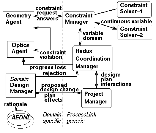
Figure I-1: ProcessLink Framework with example EPL message types and CAD
software.
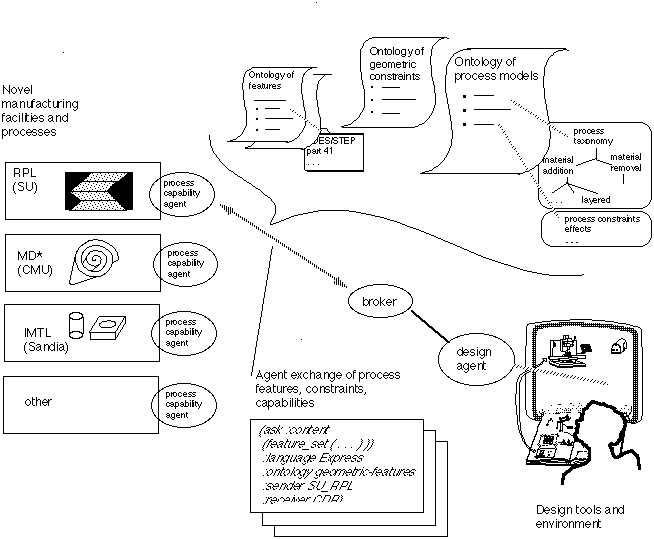
Figure I-2: An agent dialogue for generating Design Rules on Demand for a new
manufacturing process. In this case, the processes under consideration include
layered shape deposition processes and a flexible machining and welding cell.
The dialogue includes definitions of process capabilities, features and
constraints, referred to shared ontologies and standards. Process simulation
capabilities are also transported via Hot Java.

Figure I-3: Illustration of the Design Space Colonization concept relative to
missile design. Explorers of the space collect, record and analyze design
options. New technologies offer portals to new design spaces.